 CYPE Architecture: Software Bim gratuito
 IDEA StatiCa Steel: Steel connections & joints
 GEO5: Geotechnical software
 IDEA BIM: BIM structural software
 ZWCAD: 2D and 3D POWERFUL CAD
 PREF: Prestressed beams
 IDEA Detail: Details in reinforced concrete
 FIN EC: Structural Design Software
 AGACAD: Bim solutions for Revit® professionals
 IDEA StatiCa Concrete: Reinforced concrete design
 IDEA Prestressing: Calculation precast elements
 Tools for ZWCAD: Strumenti per la produttività
 EurocodeExpress: Eurocodes Calculation
 BETONexpress: Reinforced Concrete
 WOODexpress: TIMBER structures
 STEELPortalFrame EC3: STEEL Portal Frames Calculation
 SteelSectionsEC3: Design tables for Steel Sections
 3DMacro: Masonry calculation
 Histra Arches and Vaults: Historical Structures Analysis
 STEELexpress
STEELexpress: Design of Stuctural Steelwork Elements according to Eurocode 3 EN 1993:2005
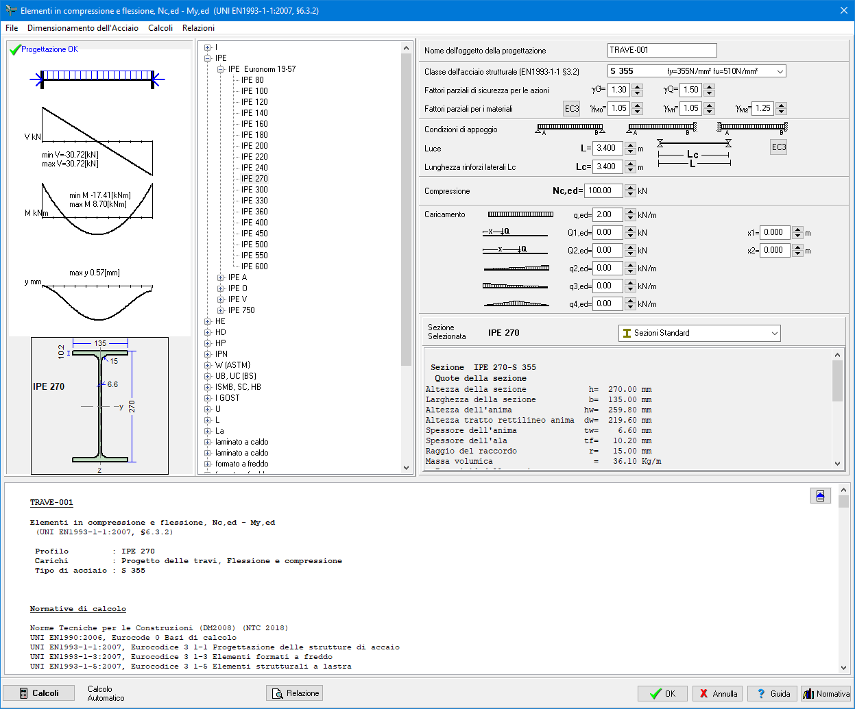
With STEELexpress you can easily design structural elements of structural steel.
Lifetime license and free updates!
A combined detailed report is produced for the designed steel components. Assumptions and references to design codes are shown in the report. The user can select the applicable National Annex. The design code parameters, as well as default values, can be adjusted by the user. Design Charts and Tables for use and understanding of Eurocode 3 are included in the program. For frame structures the program's CAD modulus automatic generates detailed drawings of the structure and the joints.
Software features
- Lifetime license and free updates
- UPDATED TO THE LATEST REGULATION
- Wide set of available structures
- User friendly input of data
- Fast results
- Every check has references to the design code paragraphs
Price list and offers
perpetual license + free updates
Contact us for you custom quote
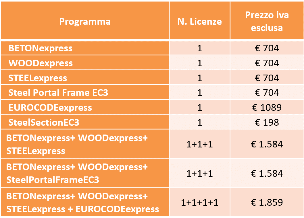
There is a special discount for WOODexpress, BETONexpress, STEELexpress customers: CONTACT US FOR A CUSTOM QUOTE
For more licenses at the same time,CONTACT US FOR A CUSTOM QUOTE
Schools, universities and institutions, please contact us.
UPDATING
Free updating to new versions from the program's Main menu/Update.
When a program has changed considerably, due to changes in Eurocodes or standards, or when new features are included, we will contact you. Such upgrades usually run 20-30% of the original program price.
SERVICES
Free Technical Support directly from the producer RUNET© Norway as
No yearly assistance/maintenance fee.
- Classification of cross-sections
- Resistance of cross-sections in single and combined actions
- Flexural and lateral buckling resistance of members.
- Design of connections.
- Design of beams, columns, roof and floor structures.
- Design one floor framesand two floor frames.
- Design of purlins and bracing systems.
- Design of footings of steel structures.
- Parameters according to National Annex of Eurocode.
- Detailed reports with references to Eurocode paragraphs and necessary drawings.
- Tables with all international steel profiles with dimensions, resistance and buckling resistance values.
- User defined steel section properties.
- Welded steel sections formed by the user.
A combined detailed report is produced for the designed steel components. Assumptions and references to design codes are shown in the report. The user can select the applicable National Annex. The design code parameters, as well as default values, can be adjusted by the user. Design Charts and Tables for use and understanding of Eurocode 3 are included in the program. For frame structures the program's CAD modulus automatic generates detailed drawings of the structure and the joints.
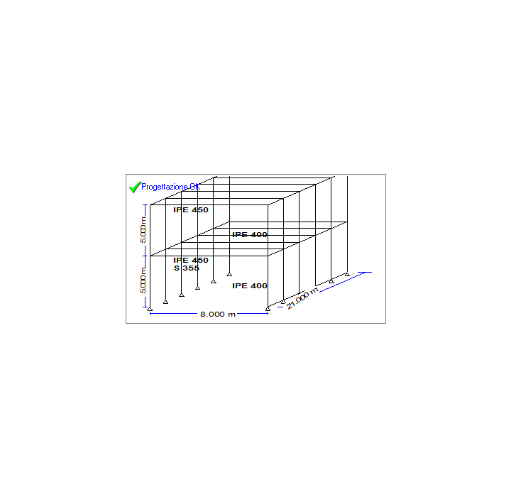
Design of steel frames
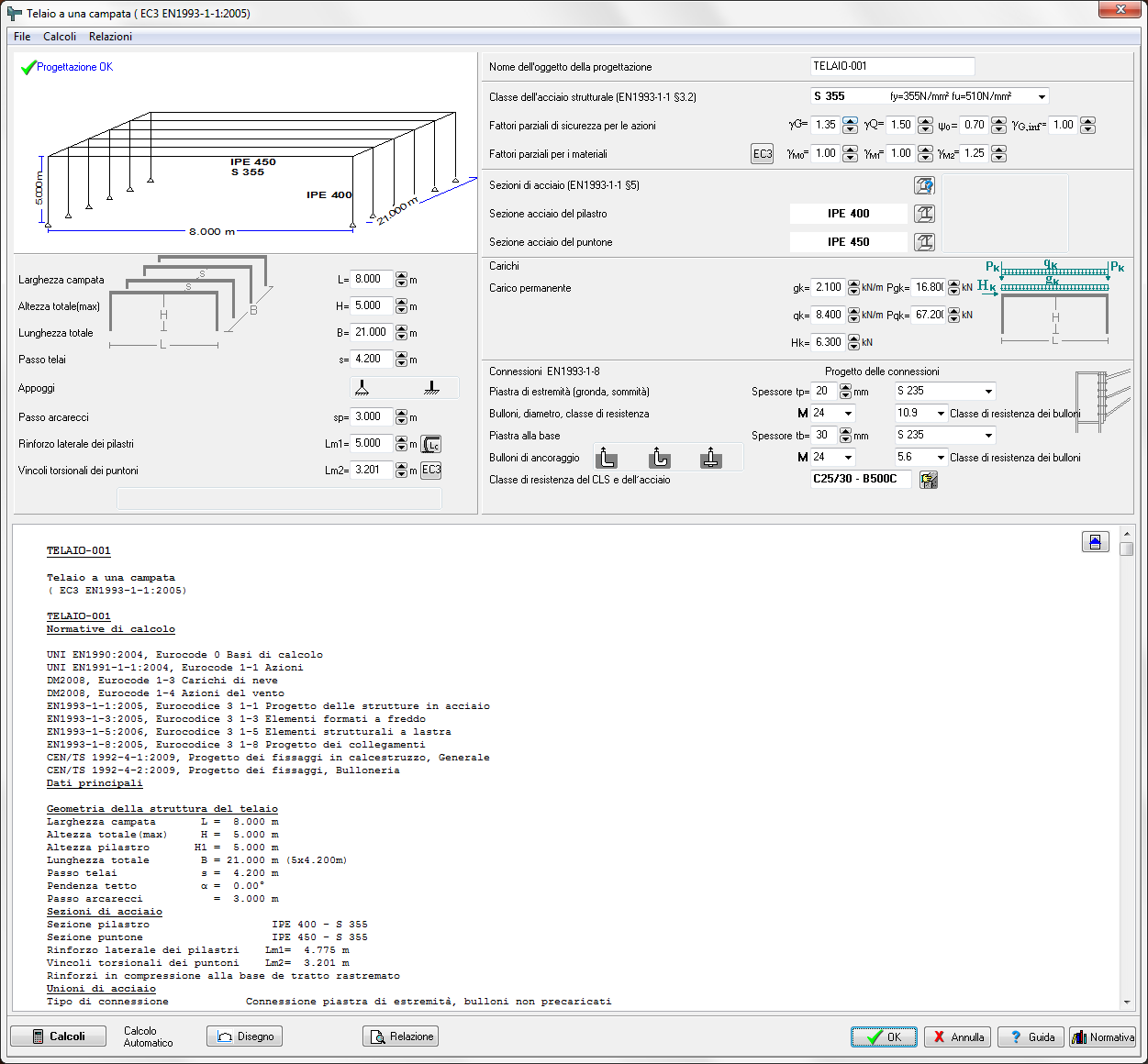
Single bay portal frames under vertical and horizontal loadings, also with concentrated loads on the columns
Single bay portal frames under snow, wind and seismic loading.
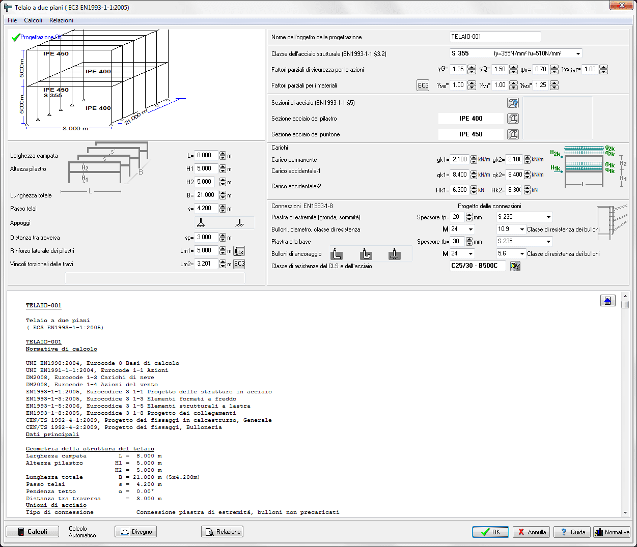
Two floor frames under vertical and horizontal loadings
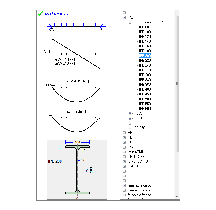
Design of Steel Beams
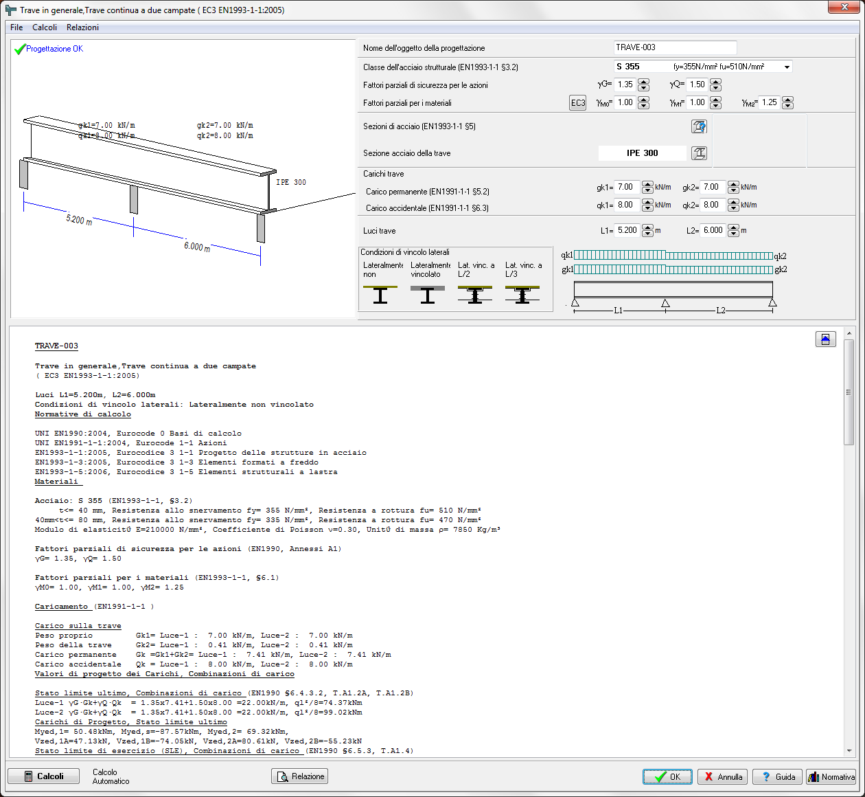
Single beams (simply supported, fixed in one end or fixed in both ends). Combination of uniform, triangular or concentrated loads. Various lateral length supports.
Floor beams of one or two spans or one span and cantilever. Laterally unrestrained, restrained at one or two intermediate points, or totally restrained.
Roof beams of one or two spans. Snow, wind pressure and under pressure, imposed load.
Purlin design. Simply supported or continuous. Laterally restrained or unrestrained.
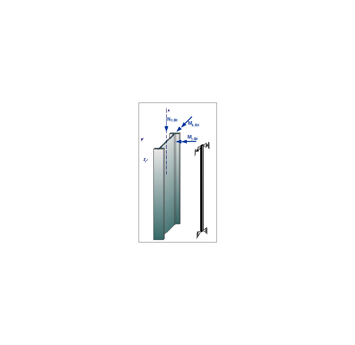
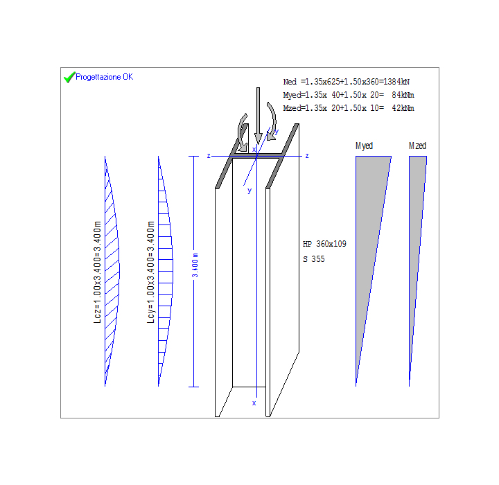
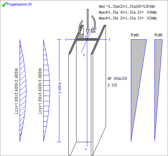
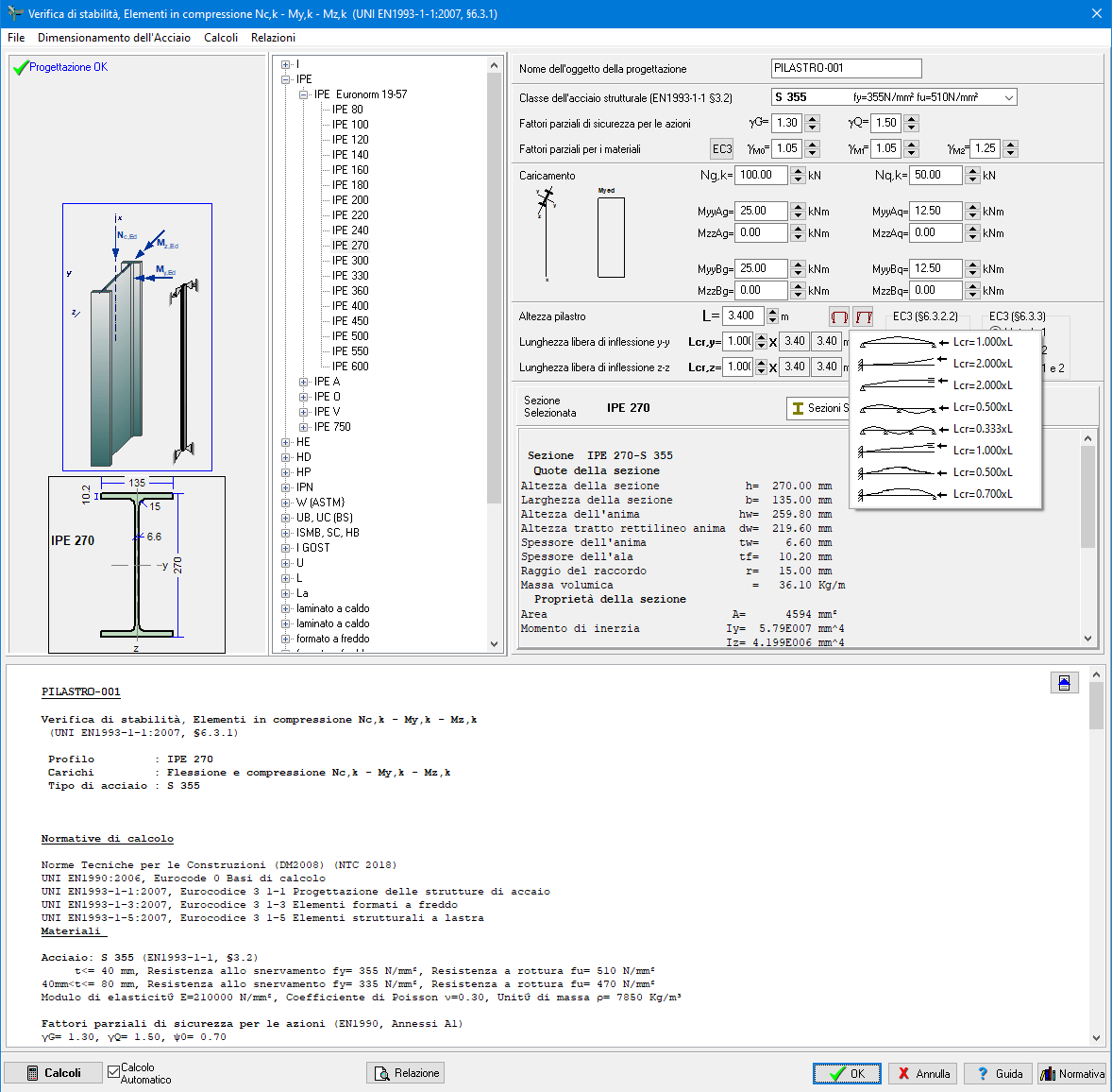
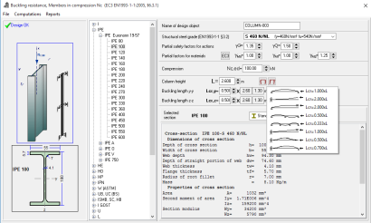
Design of Steel columns
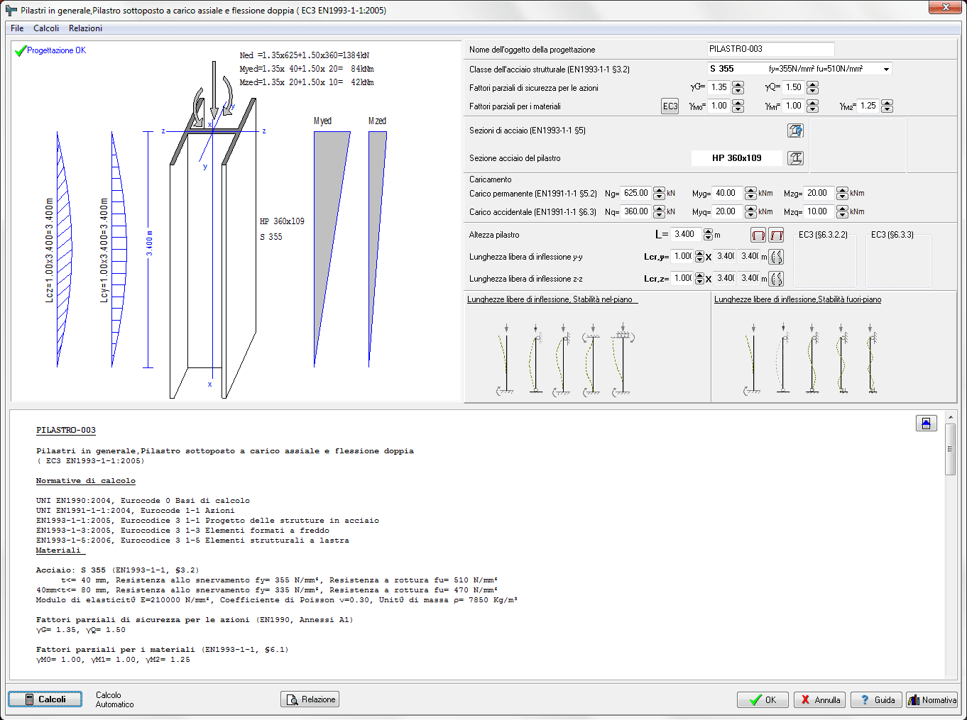
Single members in compression (various end conditions and buckling lengths).
Columns under axial load, or axial load and single or double bending.
Columns in simple constructions (simple columns, columns in braced or unbraced frames)
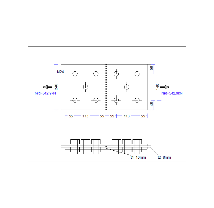
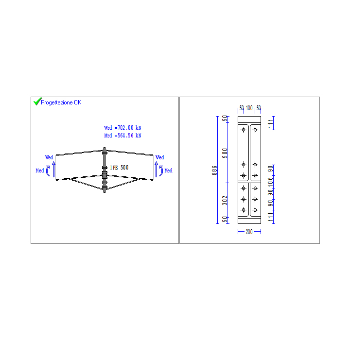
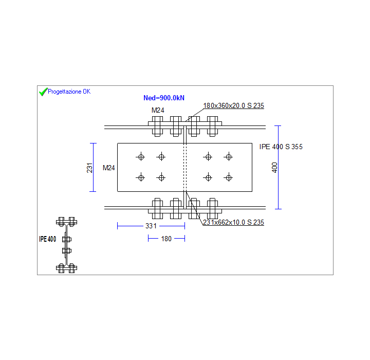
Design of bolted connections
Design of various connections according to Eurocode 3-1-8
Connections are design for specific actions, and the program selects the optimum connection geometry and bolt number and arragenment .
You may also specify the bolt number and configuration and the program computes the connection capacity
Tension connections
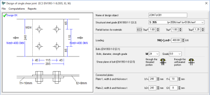
Shear joint
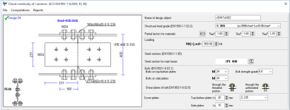
Short continuity of I section
Double shear joint
Splice joint
Beam to beam connections
Beam-continuation connection
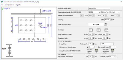
Gerber-beam connection
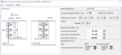
Beam-on-beam connection with web cleats
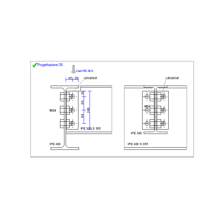
Beam to column connections
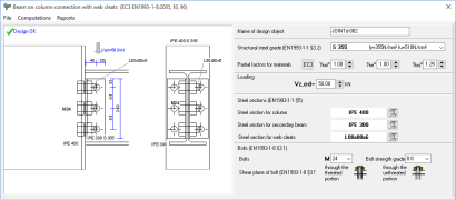
Beam on column connection with web cleats
Beam on column connection with end plates
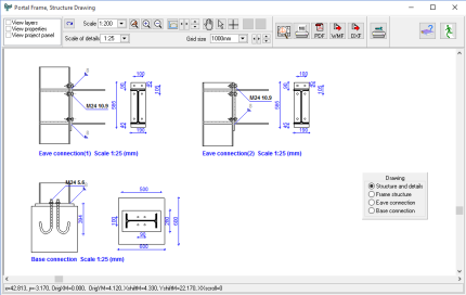
Connections of portal frames
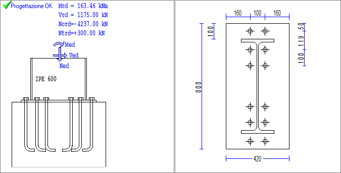
Bolted connections with end or base plate.
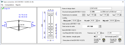
Apex connection
Eve connection with Haunch
Eve connection without haunch
Simple column base connection
Fixed column base connection
Connections made with pins
Pin ended member
Gerber-beam connection
Design of Bracing systems
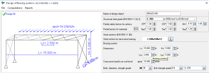
Bracing systems are required to resist transverse actions, due to wind and earthquake.
Vertical bracing system in the sidewalls between the columns.
This system transmits the horizontal transverse loads from the roof to the ground and temporary stability during the erection.
Horizontal roof bracing system
On the roof to transmit the transverse loads from the roof to the vertical bracing and to provide temporary stability during the erection.
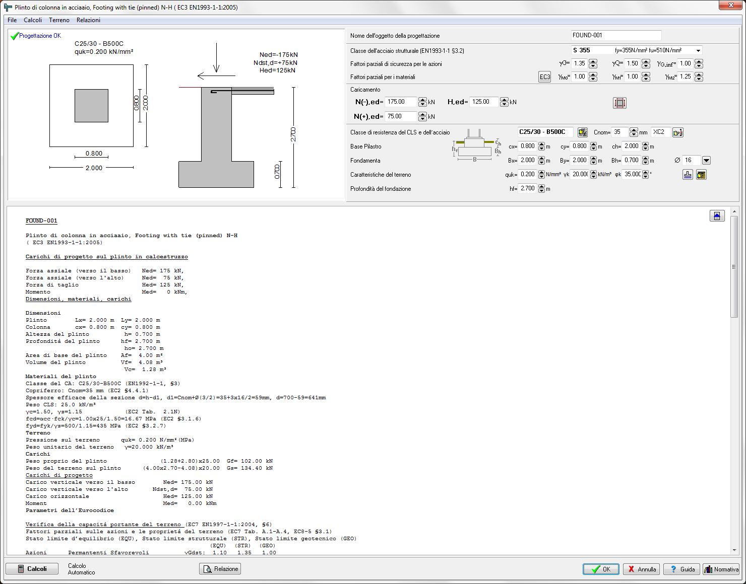
Design of footings of steel structures
Pinned footing under vertical and horizontal loading
Fixed footing under vertical and horizontal loading and moment
Footings resisting horizontal forces only with passive earth pressure
Footings with horizontal ties in order to resist horizontal forces
Design of base anchoring system
Simple base connection (vertical and horizontal forces).
Fixed base connection. (vertical , horizontal forces and overturning moment).
Anchor bolts with hooks or with washer plates.
.png)
Eurocode 4
Design of composite steel and concrete structures
EN 1994-1-1:2004 Design of composite steel and concrete structures, General rules and rules for buildings
Resistance of cross-sections
Design of steel cross section in Ultimate Limit State (ULS) for various combinations of actions.
For a selected cross section and the actions on the cross section the design the design resistance of the cross section is computed.
Single actions
Tension Nt
Compression Nc
Bending Myy, Bending Mzz
Shear Vz, Shear Vy
Double actions
Bending and compression Nc-Myy,Nc-Mzz
Biaxial bending Myy-Mzz
Compression and shear Nc-Vz, Nc-Vy
Combined actions
Compression, bending and shear Nc- Vz-My
Tension, bending and shear Nt-Vz-My
Bending and compression Nc-Myy-Mzz
Bending and tension Nt-Myy-Mzz
Axial force shear and bending N-V-M
Buckling Resistance of members
Buckling resistance and lateral buckling resistance of members
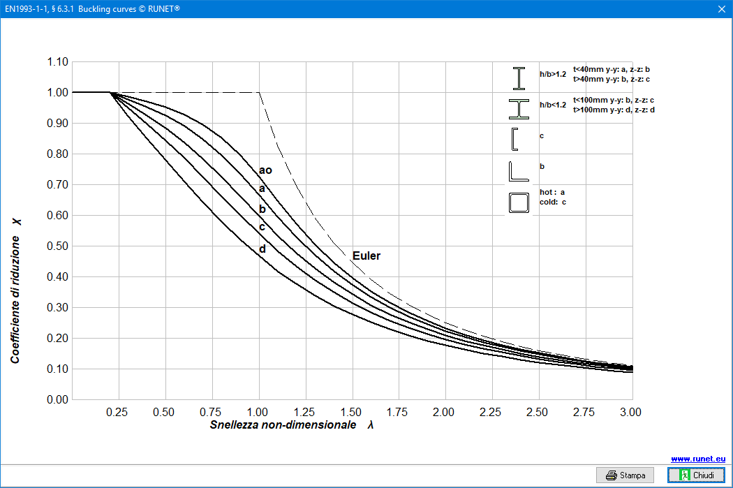
Uniform members in compression EN1993-1-1:2005 6.3.1.
Columns with axial load only
Uniform members in bending EN1993-1-1:2005 6.3.2
Lateral Buckling Resistance of members
Beams with vertical load only
Uniform members in bending and axial compression EN1993-1-1:2005 6.3.3
Columns with axial compression and end moments
Beams with vertical load and axial compression
Variety of loading combinations, end support conditions and various lateral restrained conditions.
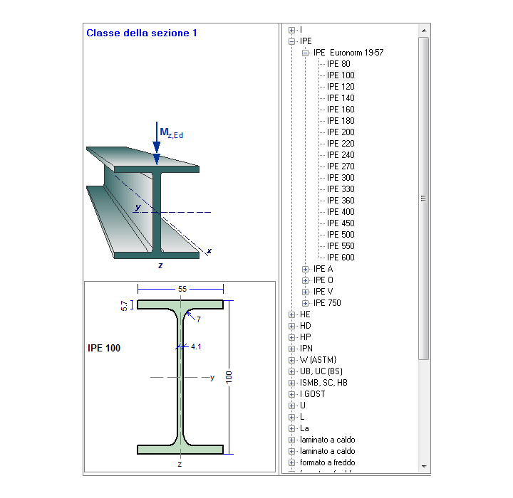
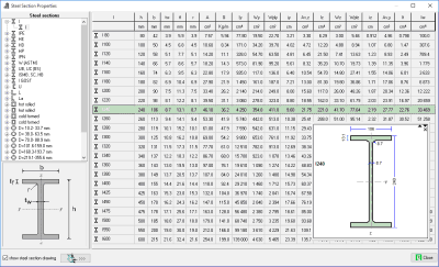
Steel Sections
Standard sections, user defined, welded sections
Dimensions, geometric properties
Classification
Resistance values (axial load, bending shear)
Buckling resistance and lateral buckling resistance for various buckling lengths
Tables of all the international steel profiles
Dimensions, properties, classification resistance values for various actions, buckling and lateral buckling resistance values.
Tables of non-standard steel sections
Section properties are defined from the user.
Tables with welded (fabricated) steel sections
The user can make the steel section by giving the dimensions and thicknesses. The geometric and strength properties are computed by the program. These sections can be used anywhere in the program for designing steelwork elements.
Basic design charts and graphs of EC3
Buckling curves, tools for computing buckling reduction factor.
Elastic critical moment for lateral buckling Mcr
Tools for computing Effective length of braced and unbraced members.
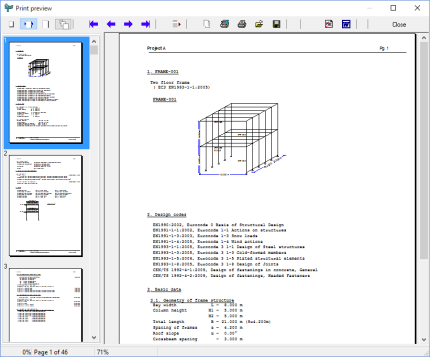
Preview and print Report
Full report preview. Drawings of the structure and the structural details for the connections. The computational errors, or inadequate dimensioning, are shown in red.
Export of all reports to PDF or Word format.
Export of all CAD drawings to PDF or DXF(Autocad) format.
Printing in Α4, Α3, Α2 paper.
Full design report preview. Detailed report with diagrams, structure and connection drawings.
References to Eurocodes paragraphs, report of analytical formulas and calculations.
Report contents and design parts can be selected.
PDF and DOC export of the report.
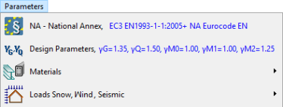
Basic Program Parameters
National Annex from EU countries.
ITALIAN NTC 2018
Materials: Structural steel, Concrete, Reinforcing steel, Soils.
Environmental loads, snow, wind, seismic
Eurocodes used in STEELexpress
EN1990:2002, Eurocode 0 Basis of Structural Design
EN1991-1-1:2002, Eurocode 1-1 Actions on structures
EN1991-1-3:2003, Eurocode 1-3 Snow loads
EN1991-1-4:2005, Eurocode 1-4 Wind actions
EN1992-1-1:2004, Eurocode 2 Reinforced concrete
CEN/TS 1992-4-1:2009, Design of fastenings in concrete, General
CEN/TS 1992-4-2:2009, Design of fastenings, Headed Fasteners
EN1993-1-1:2005, Eurocode 3 1-1 Design of Steel structures
EN1993-1-3:2005, Eurocode 3 1-3 Cold-formed members
EN1993-1-5:2006, Eurocode 3 1-5 Plated structural elements
EN1993-1-8:2005, Eurocode 3 1-8 Design of Joints
EN1997-1-1:2004, Eurocode 7 Geotechnical design
EN1998-1-1:2004, Eurocode 8 Design in earthquake environment
Engineering tools
Unit conversion
Area calculations
Section of properties
Calculation Rolled steel shapes
The software STEELexpress covers the design and analysis of structural steelwork elements according to Eurocode 3 EN 1993:2005.
In a unified environment you design steelwork elements in a simple way. The design of steel structural components cover many needs of a structural design firm. It simplifies all the repetitive and time-consuming every day calculations for concrete elements. In addition, with the analytical reports and Eurocode references, helps for engineers and engineering students to gain familiarity with design according to Eurocode 3.
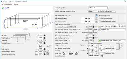
In a graphical added environment you specify the necessary dimensions, loads and design code parameters of steel components, and the design is immediately performed. Default values and checks for erroneous input values, facilitate the input data process. The detailed calculations can be viewed immediately.
The report, which is created simultaneously, shows in detail all the calculations and the design steps with references to the corresponding design code paragraphs. In case of inadequate design warnings in red colour appear in the report, and on the calculation window. The report quality is high with sketches, graphs and formulas, and with user specified title block, logos and fonts.
In one project you can create as many structural elements (design objects) as you desire. All the data are stored automatically in one file. A dedicated window helps you working with the design objects in a project. Each structural element is well marked with a name and an icon. You can edit, copy or delete design objects in a project with a click of the mouse.
You can select the design objects to be included in the final project report.
With double clicking on a design object you enter its calculation window. With right clicking on a design object you can select actions like computations, report previewing and export file, or drawing.
A help system, guides you through the use of the program and the Eurocode provisions. On-line user's manual and frequently asked questions (F.A.Q.) are included in the program.
The design code parameters and the material properties are according to the requirements of the National Annex. The user can select National Annex region. Parameters and materials can also be adjusted by the user.
Steelwork elements included in the program
- Basic design charts and graphs of Eurocode 3
- Buckling curves
- Elastic critical moment for lateral buckling Mcr,
- Effective length of braced and unbraced members
- Steel sections
- dimensions, geometric properties
- classification
- resistance values
- buckling resistance and lateral buckling resistance for various buckling lengths.
- Resistance of cross-sections for various single or combined actions
- Buckling and lateral buckling of members
- Connections of steel members
- Simple tension connections (single double shear and splice joints)
- Beam to beam connections (beam continuation, Gerber connection, connection with web cleats)
- Beam to column connections (with web cleats or end plates)
- Portal frame connections (Apex connection, eve connections simple or with hunch, Base connections simple or fixed).
- Connections with pins. (Pin ended member, Gerber beam)
- Steel Beam design
- Single beams (simply supported, fixed in one end or fixed in both ends). Combination of uniform triangular or concentrated loads. Various lateral length supports.
- Floor beams of one or two spans or one span and cantilever. Laterally unrestrained, restrained at one or two intermediate points, or totally restrained.
- Roof beams of one or two spans. Snow, wind pressure and under pressure, imposed load.
- Purlin design. Simply supported or continuous. Laterally restrained or unrestrained.
- Steel column design
- Single members in compression (various end conditions and buckling lengths)
- Columns under axial load, or axial load and single or double bending.
- Columns in simple constructions (simple columns, columns in braced or unbraced frames)
- Steel frame design
- Single bay portal frames under vertical and horizontal loadings
- Single bay portal frames under vertical and horizontal loadings, with concentrated loads on the columns
- Single bay portal frames under snow, wind and seismic loading.
- Design of bracing systems
- Vertical bracing system
- Horizontal bracing systems
- Design of footings of steel structures
- Pinned footing under vertical and horizontal loading
- Fixed footing under vertical and horizontal loading and moment
- Footings resisting horizontal forces only with passive earth pressure
- Footings with horizontal ties in order to resist horizontal forces
- Design base plate design and base anchoring system. For simple and fixed base connection
.png)
With the program you create and manipulate various design objects or structural steelwork elements. The design objects can be a variety of steelwork parts of a structure such as: beams, columns, connections, simple frame structures, footings, etc. All the program activity takes place within the main window.
Within a project you may create as many design objects as you want. All the data are saved in one project file. A common report is created. You can select the steelwork objects that you want to include in the report. The main window displays and handles all the necessary information and actions for the design objects of the project.
You can create new design objects with the action buttons at the top of the main program window.
Each design object, with a name you specified, and a characteristic icon, is shown in a list in the [Design objects] window. From this window you can regulate their appearance and the order of appearance in the report. The right side window shows the calculations of the selected design object.
By double clicking a design object you enter its calculation window, where you specify the dimensions, the loads and the design code parameters. When the object is created the parameters take the default values. All the required data are well marked with a sketch, and the appropriate dimensions. The program constantly checks for wrong or inappropriately entered values.
With right clicking a design object you can select from the popup menu actions like computation, report previewing, printing, exporting, or CAD drawing.
In front of every design object is a check box. Only the objects that are checked will be included in the common report.
I programmi vengono continuamente aggiornati in base al nuovo ambiente Windows e all'Eurocodice o agli standard su cui si basa Per le nuove versioni è possibile eseguire l'aggiornamento scaricando la nuova versione dal menu principale / Aggiorna.
La licenza è permanente e gli aggiornamenti sono gratuiti, in genere viene rilasciata una nuova versione ogni 2/3 mesi. Solo nel caso in cui vengano effettuate aggiunte importanti sul tipo di elementi da calcolare o sulle normative, viene richiesto un costo per l’aggiornamento (circa il 20%-30% del costo del programma). Per capirci, dal 2013, questo è avvenuto solo 1 volta sul BETONexpress perché sono stati raddoppiati gli elementi calcolabili, mentre ad esempio l’aggiornamento per nuove normative italiane NTC2018 è stato gratuito. A nostra discrezione.
No, non ci sono canoni di manutenzione e gli aggiornamenti sono generalmente gratuiti.
La licenza è permanente e gli aggiornamenti sono gratuiti, in genere viene rilasciata una nuova versione ogni 2/3 mesi. Solo nel caso in cui vengano effettuate aggiunte importanti sul tipo di elementi da calcolare o sulle normative, viene richiesto un costo per l’aggiornamento (circa il 20%-30% del costo del programma). Per capirci, dal 2013, questo è avvenuto solo 1 volta sul BETONexpress perché sono stati raddoppiati gli elementi calcolabili, mentre ad esempio l’aggiornamento per nuove normative italiane NTC2018 è stato gratuito. A nostra discrzione.
Richiesta codice di attivazione
Dopo l'installazione, la prima volta che esegui il programma ti verrà chiesto un codice di attivazione.
Basta premere il pulsante [e-mail a RUNET] e presto riceverai il codice di attivazione via e-mail.
Se l'antivirus blocca il messaggio, digita i numeri del codice del programma in una normale e-mail all'indirizzo indicato nella finestra di attivazione oppure compila i numeri nei campi vuoti qui sotto e inviaci il messaggio.
No, il software ha solo protezione software.
La finestra di dialogo Imposta stampante non viene visualizzata perché la stampante predefinita di Windows non esiste. Di solito ciò accade in vecchie versioni di Windows quando la stampante predefinita è una stampante Netware e non si è connessi a Netware o la stampante non è accesa.
Per risolvere il problema, collegare la stampante o modificare la stampante Windows predefinita.
Da [Impostazione relazione/ Caratteri, paragrafi ..] in basso si imposta la dimensione del testo nei grafici.
Per modificare la relazione di calcolo a piacimento è possibile esportare la relazione in un documento RTF. Aprendo poi il documento esportato con qualsiasi editor di testi puoi eseguire le modifiche desiderate.
Affinché il programma utilizzi il diametro dell'armatura specificato dall'utente, è necessario selezionare la casella accanto al diametro specificato. In caso contrario, il programma seleziona un diametro, attorno al diametro specificato, ottimizzando il rinforzo.
Questo succede se perché Windows non ha il supporto per caratteri greci installato. A seconda dell'installazione di Windows, i simboli matematici greci possono o meno apparire correttamente. Puoi aggiungere il supporto per la lingua greca in Windows: Vai in [Impostazioni / Pannello di controllo / Opzioni internazionali e della lingua / Avanzate]. Altrimenti vai al menu File / Supporto caratteri greci e scegli la tua lingua senza supporto per simboli matematici. Quindi i simboli matematici appariranno esplicitamente, come phi, alpha, beta ecc.
Quando provo a visualizzare l'anteprima della relazione, viene visualizzato il messaggio "Errore stampante ...".
Per visualizzare l'anteprima della relazione, è necessario che nel sistema sia presente una stampante valida. Di solito ciò accade in vecchie versioni di Windows quando la stampante predefinita è una stampante Netware e non si è connessi a Netware o la stampante non è accesa. Per risolvere il problema, collegare la stampante o modificare la stampante Windows predefinita.
Da Impostazione Relazione / Varie impostare i vari rientri.
STEELexpress Trial Download
Please fill in the form below and we will send you an email with the link to download the FREE version of the software and all the instructions to the email address you entered.
Information request
Please fill in the following form, our staff will answer as soon as possible to the email address you entered.
News, events and promotions

IDEA StatiCa festeggia i suoi 10 anni di CBFEM e dal rilascio di IDEA Connection!
UN DECENNIO DEDICATO ALLA PROGETTAZIONE AVANZATA DELLE CONNESSIONI Festeggia con noi i 10 anni di progettazione delle connessioni con IDEA StatiCa e…

IDEA StatiCa festeggia i suoi 10 anni e rilascia la nuova v24.0
E' stata uscita la nuova versione 24.0 di IDEA StatiCa. Festeggiamo i 10 anni dal rilascio del metodo CBFEM e di IDEA StatiCa Connection e…

FIERA SED | CASERTA | 11 -13 Maggio 2023
Saremo presenti al SED 2023 che si terrà a CASERTA dall'11 al 13 Maggio. Eiseko ti permetterà di partecipare a…