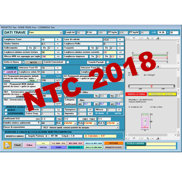
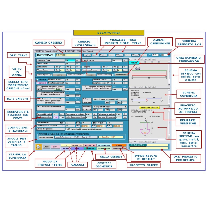
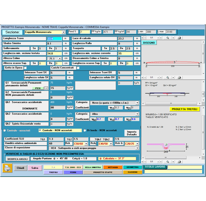
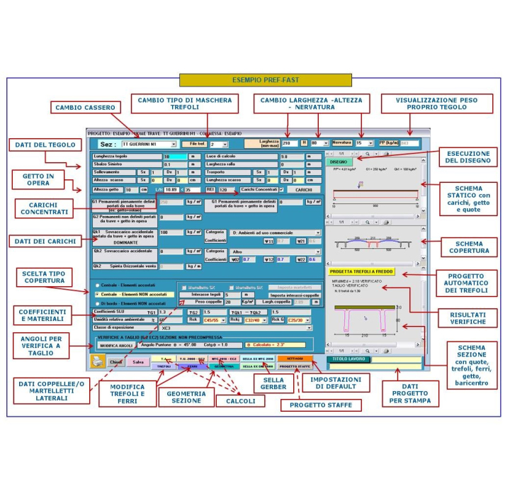
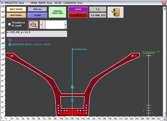
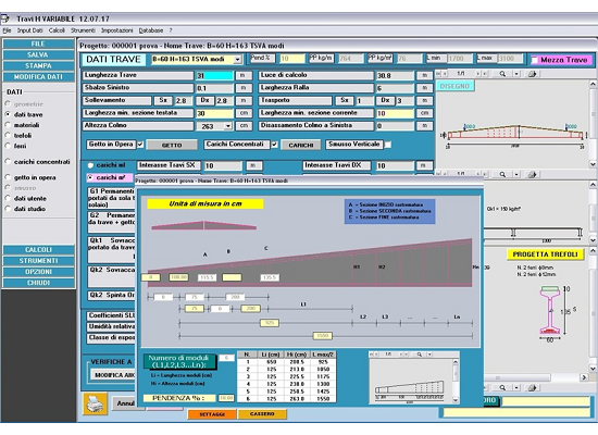
 THE FASTER IN THE WORLD PROGRAMS FOR CALCULATION, DRAWING AND ESTIMATION OF PRESTRESSED AND REINFORCED CONCRETE BEAMS OF ANY SHAPE
AVAILABLE IN ENGLISH, SPANISH, ITALIAN. OTHER LANGUAGES UPON REQUEST
Always updated to the new rules: Calculations according to Eurocodice 2 UNI EN 1992-1-1 : 2005 and NTC 17-01-2018 or D.M.14–January–2008.
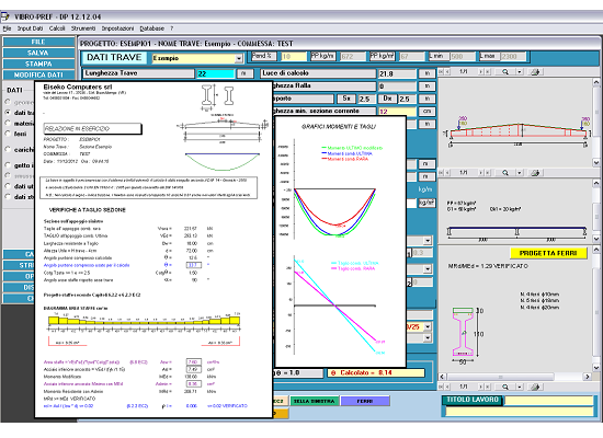
Output of tables of the shearing and bending stress along the length of beam, exhaustive or brief calculation reports, your own choice. Calculation steps explaned in the manuals with real examples. Output with the most important value evidenced for a fast and easy check. Values out of limits are highlighted.
THE PROGRAM IS COMPOSED BY MODULES: CHOOSE YOUR PREFERRED MODULES TO MAKE THE BEST PREF PACKAGE FOR YOUR SPECIFIC NEEDS
Software features
- Calulations according to the new rules, always
- Check and design of beams of any shape
- User friendly input and fast results
- Complete results, highlighted and easy to check
- Workingshop drawings with bills and parametric reinforcement
- Technical support and updates included
- Can be used by proposal department
- Custom programs tailored for you
Modules
The program verifies and checks iteratively prestressed pre and post tensed beams and reinforced concrete beams of any sections according to Eurocode 2 UNI EN 1992-1-1 : 2005 and Italian NTC2018.
The verification is made in a series of sections with constant step along the whole beam length + the first prestressed section + the most stressed section for bending + the last prestressed section.
The beam can have CAST IN PLACE and POINT LOADS.
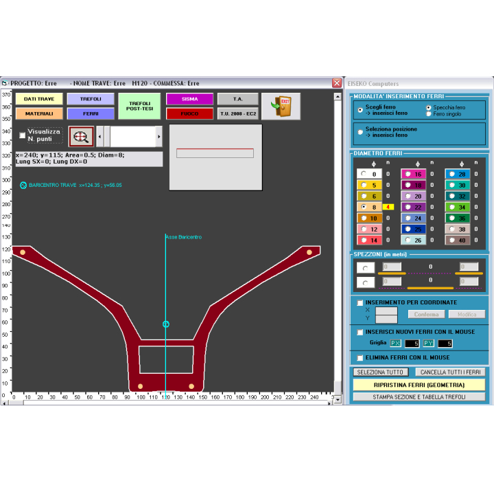
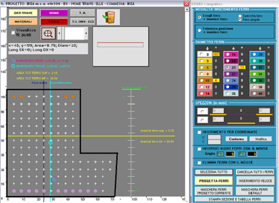
User can input piece of rebars in any point of the beams
The program will also verify the transitional phases: the draft, lifting, lifting / transport after a storage period
In each section the programs checks main traction and compression sigmas on the centre of gravity and shows the minimum distance where the stirrups should be placed. Superior and inferior reinforcement is always calculated, to absorb the tractions as requested from Regulations.
AUTOMATIC PROJECT OF THE NEEDED STRANDS (for prestressed beams) The program designs the minimum needed strands FOR BREACKING VERIFICATION
AUTOMATIC DESIGN OF THE REBARS (for reinforced concrete beams): The program automatically designs the needed rebars as for breaking verification. Anyway all the others check are done in the various phases. After the calculation, or after the design of rebars, user gets automatically the beam scheme with calculation results.
AUTOMATIC PROJECT OF THE NEEDED REBARS AND STIRRUPS FOR SHEAR AND TORSION
There is the possibility to calculate any section chosen from the user, with the control of main tau and sigma of traction on the whole height of the section.
LOCAL VERIFICATION (Check of the load on a projecting tooth + Check of tooth and suspension + Check suspension only) – For Constant H Beams
SHEAR VERIFICATION in the not-prestressed section on support, following the method “variable strut inclination method”
Display of Constraint reactions Rare and Ultimate left and right (also shown in the calculation report).
Editing of a database of the most used roof elements for the automatic calculation of G1, so that the user doesn’t need to look through weight tables each time
Input of loads on beam using m2 or m, user choice
USE DIAGRAMS research of the span-capacities diagram, given a certain reinforcement
ANY TYPE OF CROSS-SECTION Input by points, trapeziums, by DXF, automatic parametric sections or we can input your personal mould for customized beams
Automatic calculation of all the geometrical characteristics
VERIFICATION OF OVERHANG SUPPORT
VERIFICATION IN PARTIAL PRESTRESS
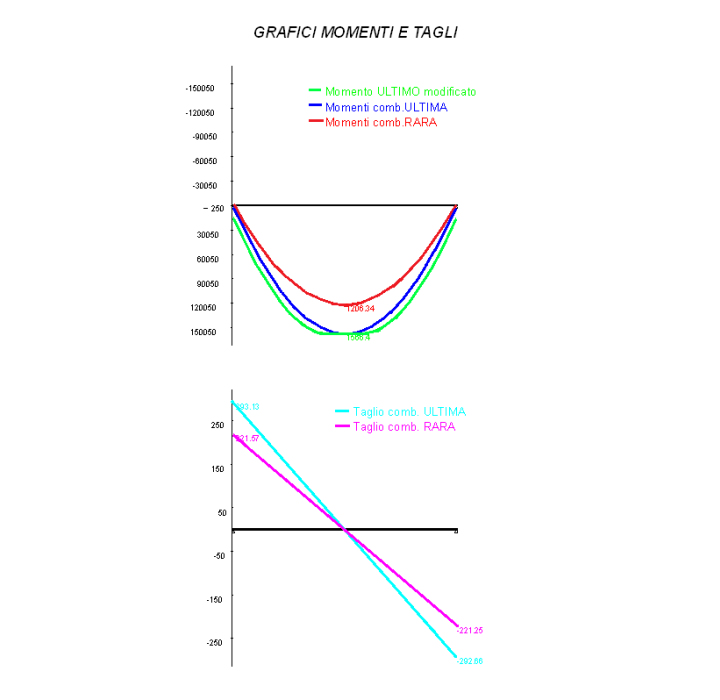
Moments and shear graphs
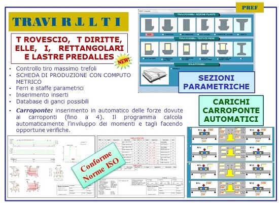
Crane: automatic input of the forces due to cranes (up to 4). The program calculates automatically moments and shares after the needed checks
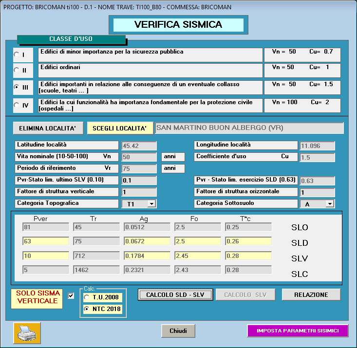
SEISMIC VERIFICATION
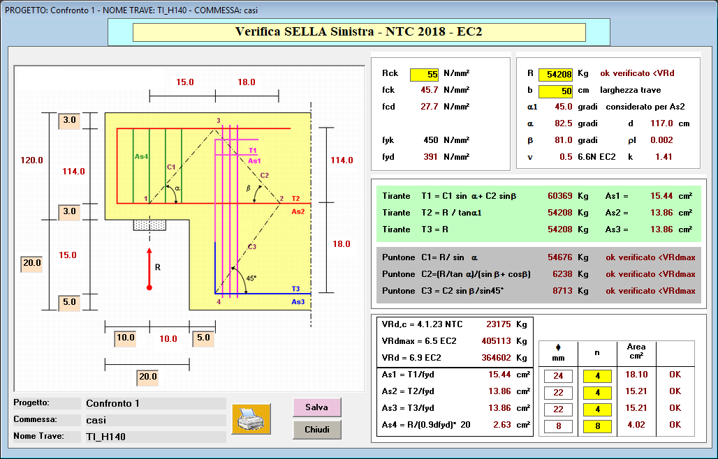
Verification of GERBER SUPPORT
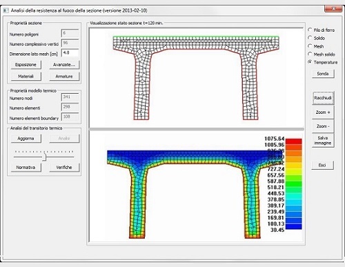
FIRE VERIFICATION (optional module)
SNOW-WIND LOADS for each Italian location for any load situation.
USE DIAGRAMS research of the span-capacities diagram, given a certain reinforcement
Reports and tables can be exported as: DOC, RTF, PDF, HTML
Fast check or results with highlight of eventual values over the limits of the Rules, any values NOT verified are indicated in red, while the values shown in blue are the values within the limits
Graph of the minimal needed area of stirrups along the whole beam
Easy and graphic management of strands, rebars and sheaths.
For users that works for more companies, it is possible to save all the default data and the parameters depending on the Company in "Criterions", so that it is easier and fast to switch from a job to another without worring about all settings. For example., it is possible to save any number of lifting ans transportation schemas.
It is possible to switch from one section to another for the verification in a few seconds and immediately see if it is satisfied or not.
Handy starting menu
Settings of defaults data can fasten the inputs of the most used configurations of beams
SCHEME OF THE BEAM: in every moment current section, cast in place if present, rebars, pre+post tensed strands and calculation results are displayed to always keep the situation under control.
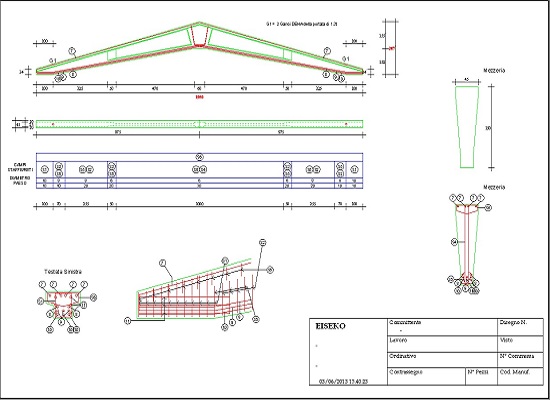
The program automatically generates the WORKINGSHOP DRAWINGS with the bill of materials, according to the results of the checks
Lots of parametric rebars and stirrups
FREE ADD-INS FOR ALL PROGRAMS engineers can easily and quickly make daily calculations
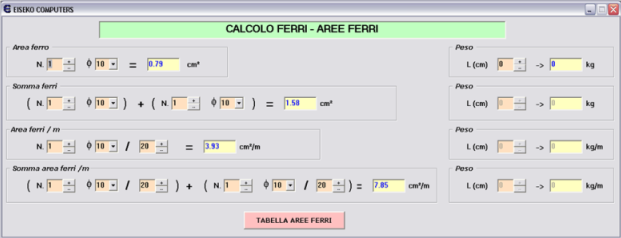
- CALCULATION OF THE REBARS AREAS (for one or more rebars, to add them and to calculate the rebar area/m)
- TABLE OF REBAR AREAS
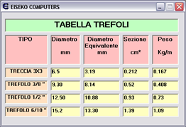
- TABLE OF STRAND AREAS
- UNIT OF MEASURE CONVERSION
- SEISMIC PARAMETERS
- SNOW-WIND LOADS for each Italian location for any load situation.
SO FAST IT CAN BE USED ALSO IN THE QUOTING STEP
Lots of enhancements are made according to customer request
Available Languages : Italian, English, Spanish
TECHNICAL SUPPORT ALWAYS INCLUDED IN THE PROGRAM PACKAGE
HELPFULNESS AND FLEXIBILITY
Eiseko Computers provides technical support together with programs, because each single customer has the right to reach immediately all the answers to any question, from a simple information to a solution for a calculation or a technical problem.
People who develop software, both engineers and software experts, are available for our customers for trouble fixing, explanation of procedures, information or tips: how to better use the software, which Rules are used and how, why you get a particular result, but also support for installation or updates.
Supported languages: Italian, English, Spanish.
SOFTWARE ENHANCEMENS BY USER REQUEST any request made by the users has a fast track for the developing of our software

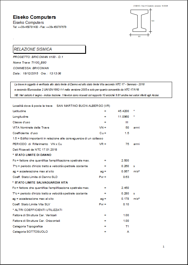
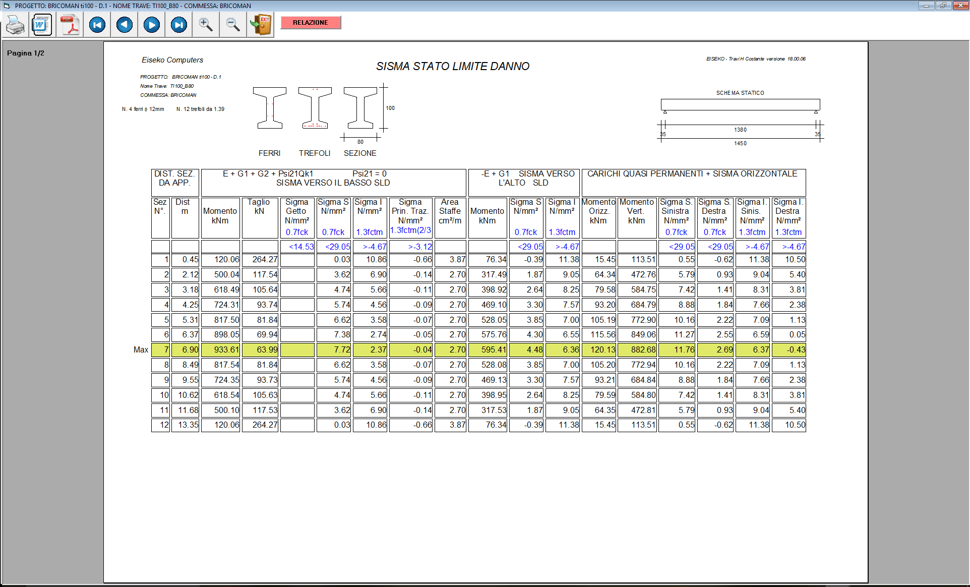
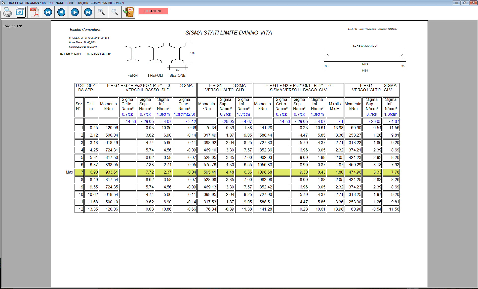
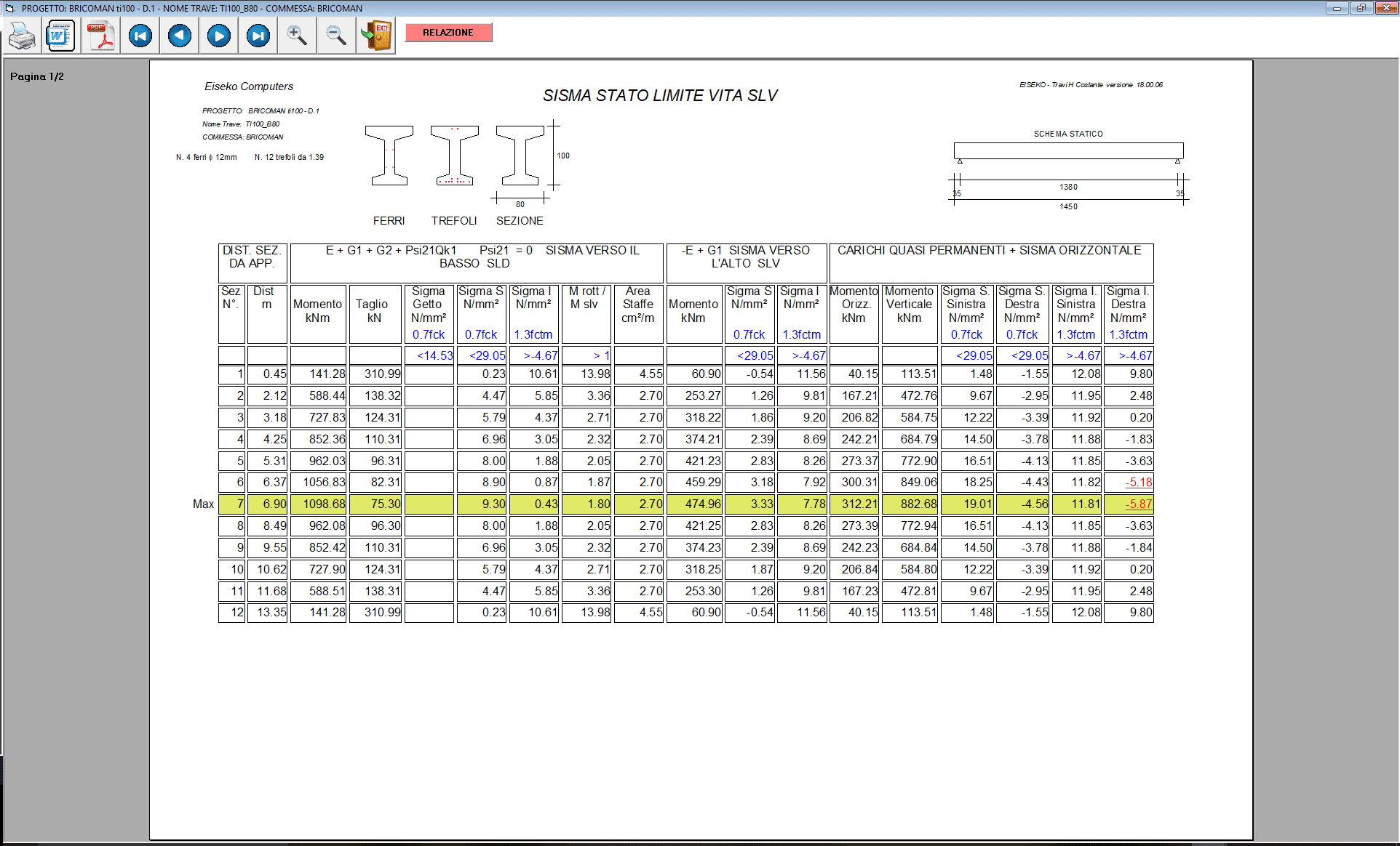
Seismic verification included in each Eiseko's program
Verification according to NTC 17/01/2018 and D.M. 14/01/2008
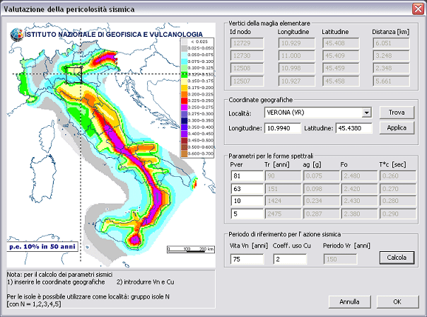
- Graphic visualization on the map of the seismic locations according to the New Seismic Classification
- Automatic latitude, longitude and needed coefficients once the user choses the location
- Automatic calculation of the Seismic Dangerousness of the location
- Seismic Analysis with Project Spectrum calculation, for each limit condition (Limit State of operation, Damage limit state, Limit state of collapse prevention, Life limit state)
SEISMIC MAP:
FORM FOR THE SEISMIC VERIFICATION:
FREE ADD-INS in ALL PROGRAMS
engineers can easily and quickly make daily calculations
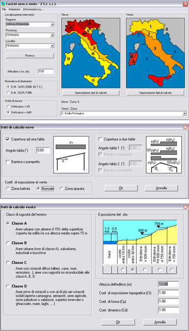
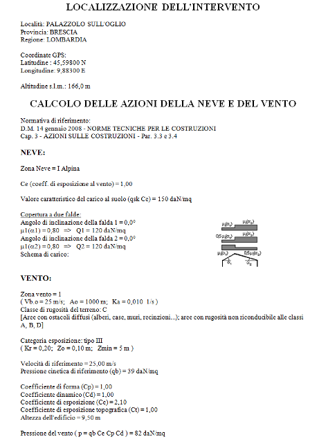
SNOW-WIND LOADS for each Italian location for any load situation
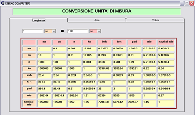
UNIT OF MEASURE CONVERSION
SEISMIC PARAMETERS
Assessment of seismic hazard: input the name of the location and the program automatically finds latitude and longitude and the seismic parameters of the indicated site
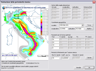
TABLE OF REBAR AREA
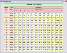
TABLE OF STRANDS AREA
CALCULATION OF THE REBAR AREAS
To calculate the area of one or more rebars, sum them and calculate the area of rebars/m (in cm2 o cm2/m ). Weight calculation of the rebars.
CALCULATION OF THE GERBER SUPPORT
RIFERIMENTI
Eurocodice 2 – Progettazione delle strutture in calcestruzzo
-UNI EN 1992-1-1:2005 Parte 1-1: Regole generali e regole per gli edifici
-UNI EN 1992-1-2:2005 Parte 1-2: Regole generali - Progettazione strutturale contro l'incendio
-UNI EN 1992-2:2006 Parte 2: Ponti di calcestruzzo - Progettazione e dettagli costruttivi
-UNI EN 1992-3:2006 Parte 3: Strutture di contenimento liquidi
NORMATIVE ADOTTATE (l'utente può scegliere la normativa di riferimento)
- Il calcolo della trave può svilupparsi agli Stati Limite secondo l'Eurocodice 2 UNI EN 1992-1-1 nella versione 2005 e solo per quanto consentito da NTC 17/01/2018
- Il calcolo della trave può svilupparsi agli Stati Limite secondo l'Eurocodice 2 UNI EN 1992-1-1 nella versione 2005 e solo per quanto consentito da DM 14/1/08
- Il calcolo della trave può svilupparsi alle Tensioni Ammissibili secondo il D.M. 14/2/92, come consentito dal D.M. 9/1/96.
SCHEMA DI CALCOLO
Il vincolo è il semplice appoggio con la possibilità di avere sbalzi alle estremità.
Si può aggiungere un getto in opera, per portare i sovraccarichi, che può essere di forma complessa. Pensa il programma ad omogeneizzare il getto in opera alla trave, tenendo conto delle diverse resistenze del calcestruzzo.
Partendo dall'appoggio sinistro è verificata la zona precompressa della trave in una serie di sezioni fino all’appoggio destro , di queste evidenzia la sezione più sollecitata a flessione.
Le cadute di tensione sono calcolate nel baricentro dei trefoli contenuti nei 2/3 inferiori di trave.
Il calcolo a rottura è eseguito in maniera esatta basandosi sui diagrammi di rottura dei trefoli forniti dal produttore degli stessi.
In ogni sezione sono controllate le sigma principali di trazione e compressione sul baricentro e viene espressa la distanza minima cui devono esser poste le staffe. E’ sempre calcolato, inferiormente e superiormente, l’acciaio per assorbire le trazioni come da regolamento.
Il programma effettua anche la verifica delle fasi transitorie: lo sformo, il sollevamento allo sformo, il sollevamento/trasporto dopo un periodo di stoccaggio.
La sezione di appoggio, in assenza di sbalzo, è considerata non precompressa.
È aggiunta una routine di verifica di una singola sezione di trave, col controllo delle tau e delle sigma principali di trazione su tutta l’altezza della sezione. È infine possibile, scelta una particolare armatura, trovarne il diagramma di utilizzo, naturalmente questo calcolo non considera i concentrati.
RELAZIONE
Il risultato appare a video nella cosiddetta “Stampa di servizio” che è suddivisa in tre parti: verifica in campata, verifica all’appoggio, verifica nelle fasi di movimentazione.
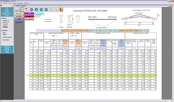
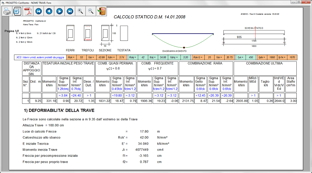
A video vengono prodotte la tabella con le verifiche agli stati limite di esercizio ed ultimi in varie sezioni lungo la trave, la verifica sull’appoggio più sollecitato e la verifica a trasporto.
Nelle relazioni e tabelle:
I valori in azzurro indicano le condizioni che il calcolo deve rispettare (es: sigma min, sigma max).
I valori in rosso indicano le verifiche non soddisfatte.
I valori in viola con riquadro indicano i valori delle staffe e dei ferri da inserire.
Indicazione delle Reazioni vincolari Rara e Ultima destre e sinistre
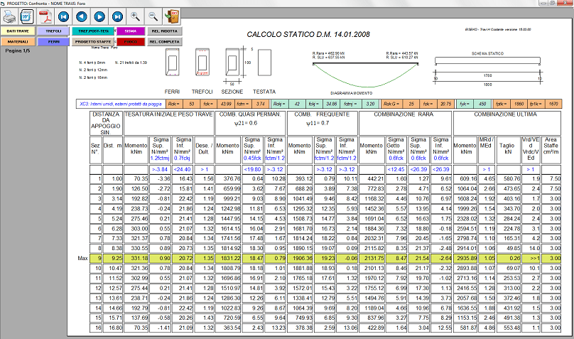
La verifica viene effettuata in una serie di sezioni disposte a passo costante dal programma a cui vengono aggiunte la prima sezione precompressa, la sezione più sollecitata e l’ultima sezione precompressa.
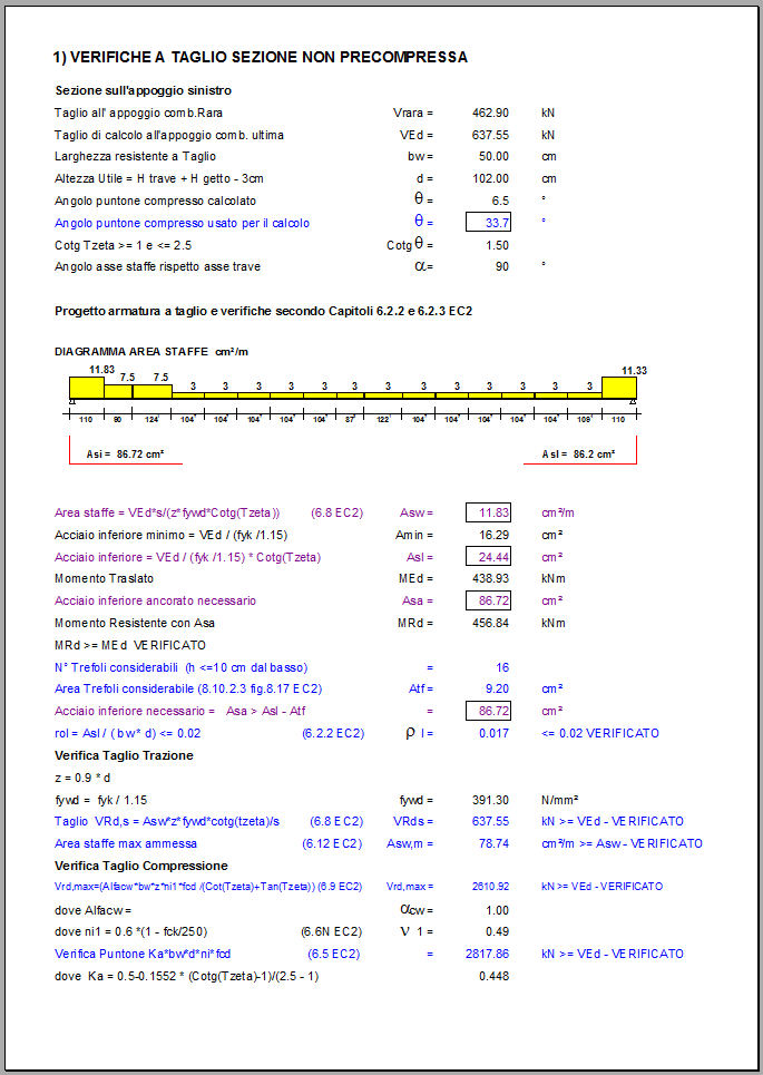
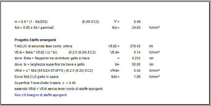
Nella pagina successiva viene visualizzata la verifica a taglio dell’appoggio più sollecitato.
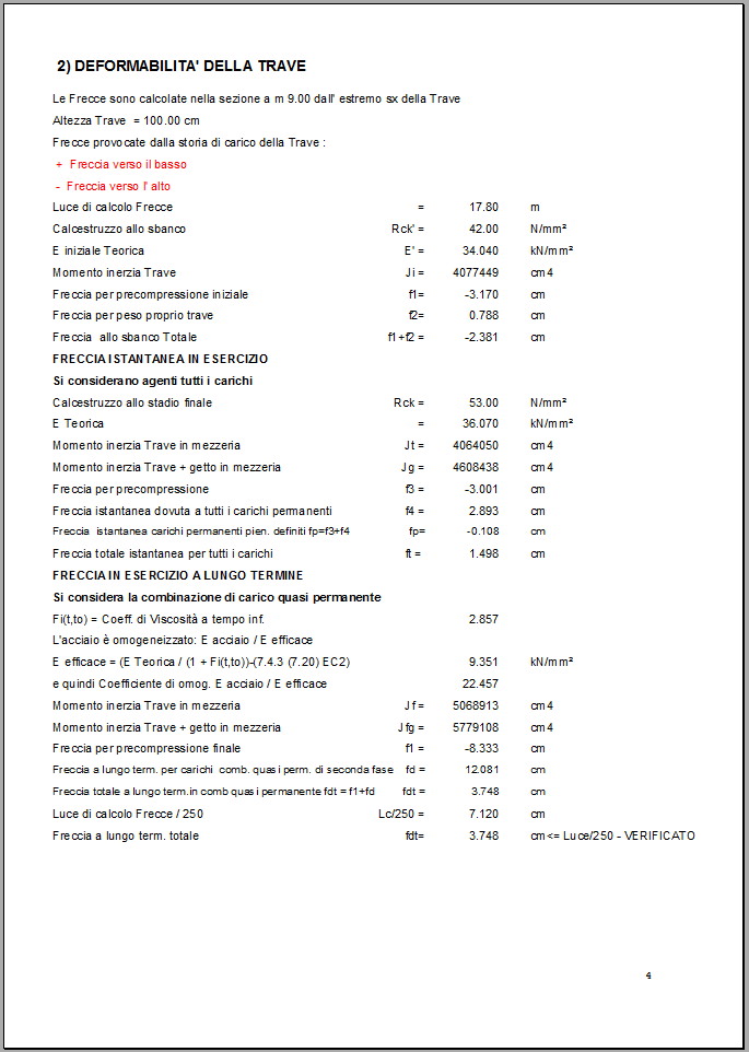
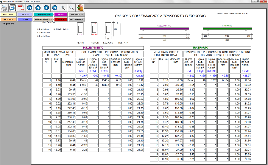
Nel sollevamento e trasporto le verifiche sono fatte in una serie di sezioni precompresse a partire dalla testata sinistra.
Le verifiche sono effettuate secondo l’EC2 per quanto consentito dal DM 14/01/08.
GRAFICO DELLE AREE MINIME NECESSARIE LUNGO TUTTA LA TRAVE
VERIFICA IN PRECOMPRESSIONE PARZIALE
Il programma passa al calcolo in precompressione parziale se nel corso delle verifiche le tensioni all’intradosso della sezione superano il limite a trazione valido per il calcolo a sezione interamente reagente (fctm/1.20).
Il calcestruzzo non viene più considerato reagente a trazione così come si fa nel calcolo delle travi in calcestruzzo non precompresso, la trave viene sollecitata con il momento di esercizio agente contemporaneamente con lo sforzo dovuto alla precompressione.
Quando la sigma massima a trazione della sezione supera la sigma limite a trazione del calcestruzzo, si ha il trasferimento immediato di tutta la trazione dalla zona tesa della sezione in calcestruzzo alle armature, con la conseguente apertura delle fessure. Per limitare la dimensione delle fessure e l’incremento di tiro sui trefoli, il programma aggiunge ferro lento (l’utente è avvisato con un messaggio a video) ponendo un ferro ø12 per ognuna delle posizioni possibili che si trovano nella fila più bassa della maschera ferri: nell’esempio il programma ha a disposizione due posizioni nella fila più bassa e quindi inserisce due ferri ø 12 per un’area complessiva di 2.26 cm2.
Non si tratta di un’armatura “da normativa”, ma solo di una proposta di soluzione del problema partendo da un minimo di armatura inferiore.
VERIFICA CON SBALZI
Se la trave è dotata di sbalzi significativi, cioè aventi dimensioni superiori alla lunghezza di diffusione della precompressione, che in genere è circa un metro (vedi anche paragrafo “Sistema di calcolo”), il programma, alla verifica in esercizio di cui al paragrafo “Calcoli”, aggiunge la verifica con le combinazioni di carichi che danno le sollecitazioni massime sugli sbalzi e minime fra gli appoggi.
La principale differenza rispetto alla tabella di cui al paragrafo “Calcoli”, che è calcolata con i carichi minimi sugli sbalzi e massimi in campata, è che in questo caso sono riportate le verifiche anche su alcune sezioni precompresse sugli sbalzi.
.png)
PROGETTO DELLE STAFFE A TAGLIO + TORSIONE E FERRI ALL’APPOGGIO
E’ possibile eseguire il progetto delle staffe della trave calcolata.
Nella relazione e nella tabella di calcolo vendono visualizzate le staffe necessarie lungo tutta la trave, con un grafico giallo rappresentante l’area di staffe minima necessaria calcolata dal programma (l’ultima colonna delle tabelle di servizio). L’utente può inserire le staffe effettive della trave, modificandole dinamicamente con questo comodo ambiente grafico, finché non sono verificate come nell’immagine seguente.
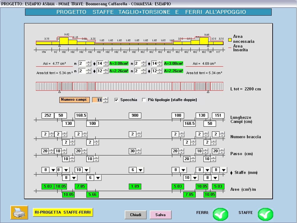
Più tipologie di staffe (staffe doppie): Per avere due tipologie disponibili per ogni campo.
VERIFICA ESERCIZIO SEZIONE A PIACERE
È possibile eseguire il calcolo di una sezione singola a scelta dell’utente, purché precompressa, e vedere la relativa tabella dei risultati.
Verifiche a Taglio nella sezione sull’appoggio, secondo il metodo del “Puntone variabile”
Secondo il metodo del puntone variabile, l’utente, come previsto dall'Eurocodice 2, ha la possibilità si scegliere per le verifiche a Taglio diversi angoli del Puntone compresso compresi tra 45° e 21°.80.
Alcuni valori già fissati per comodità, possono essere scelti direttamente dall’utente come valori da usare nel calcolo (45°, 33°.69, 26°.57, 21°.80), in alternativa si può inserire l’angolo desiderato ed infine si può optare per il calcolo automatico dell’angolo da parte del programma (J=variabile calcolato) in cui il valore dell’angolo è tale da avere contemporaneamente la rottura del calcestruzzo e dell’acciaio.
Quando si sceglie l’opzione del calcolo automatico dell’angolo, il programma, come da norma, confronta il valore calcolato con i limiti minimo di 21°.80 e massimo di 45°: se il valore calcolato dovesse essere inferiore al minimo allora verrebbe posto uguale a 21°.80, se invece dovesse essere superiore al massimo in questo caso verrebbe posto uguale a 45°.
La configurazione riportata sopra è quella di default, dove le formulazioni del Testo Unico e dell’Eurocodice 2 sono equivalenti tra loro nel caso in cui J = 45° e a meno del coefficiente n dell’Eurocodice 2.
E’ possibile anche scegliere n=n1, previsto in Eurocodice 2, in cui viene sovrastimata la resistenza del calcestruzzo di un 20% e contemporaneamente diminuita la resistenza dell’acciaio di un altro 20% (fywd=0.8*fyk/1.15). Potrebbe essere utile nel caso in cui sia il calcestruzzo ad andare in crisi e non si possa variare la sezione o i materiali.
VERIFICA LOCALE
Verifica di carico su un dente sporgente Inserisco i dati geometrici del dente e il carico su di esso (su uno dei due lati) con la larghezza della sua impronta. Il programma tiene conto della diffusione del carico e fa vedere anche a video la staffatura necessaria.
Verifica dente e sospensione Se il dente è sul lato inferiore della trave (come accade nella larga maggioranza dei casi) associato all’azione del carico sul dente c’è un effetto di sospensione, quindi oltre alla spunta su “DENTE” bisogna aggiungere la spunta su “SOSPENSIONE”. Il programma inserisce automaticamente un carico doppio di quello sul dente, poiché la sospensione è vista dal programma come agente su entrambi i lati dell’anima della trave. La diffusione del carico è quella calcolata per il dente. La staffatura di sospensione è confrontata con quella necessaria dal calcolo della trave e il programma stampa la maggiore delle due.
Verifica sospensione soltanto È necessaria nel caso di carico direttamente appeso all’anima della trave. Inserisco solo i valori del carico sospeso e della sua impronta, in questo caso il programma non deve calcolare la diffusione del carico. La staffatura di sospensione è confrontata con quella necessaria dal calcolo della trave e il programma stampa la maggiore delle due.
The PREF package is sold with a new system: rather than buying a single module (prestressed beams, vibrated beams, hollowcores, etc) or a single update, we offer the use of all the programs with a Subscription with a little annual fee.
With this contract you have a right to all the updates and new releases of all the programs and to the technical support.
More set of subscriptions available: with or without fire verification add-in, with a little number of main programs up to the full set.
CONTACT US FOR A FREE CUSTOM QUOTE
PACKAGE ALWAYS INCLUDES TECHNICAL SUPPORT AND PROGRAMS UPDATE.
- Updates from our website of all the programs under subscription
- Support via internet remote connection
- Support via Email
- Support via Skype
- Support by phone and in our offices
- Possibility to ask for new functionality and enhancements
EISEKO COMPUTERS' PROGRAMS
- Constant H prestressed beam with pre-tensed and post- tensed strands
- Variable H prestressed beam
- HOLLOWCORES
- Prestressed R, L, Reverse T beam, T beam, I beam and PREDALLES with Torsion and Gerber support, CRANE and DRAWING
- Constant H REINFORCED CONCRETE BEAM
- Variable H REINFORCED CONCRETE BEAM
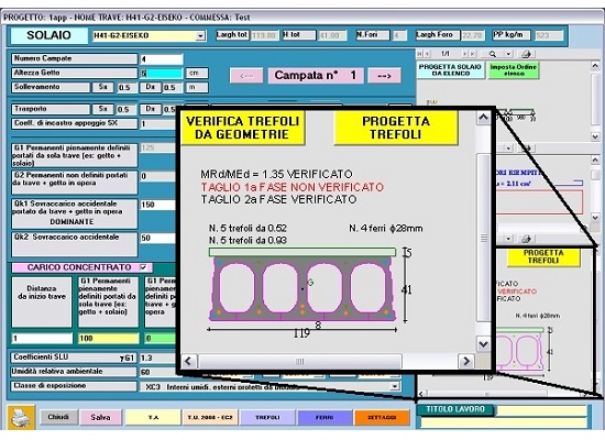
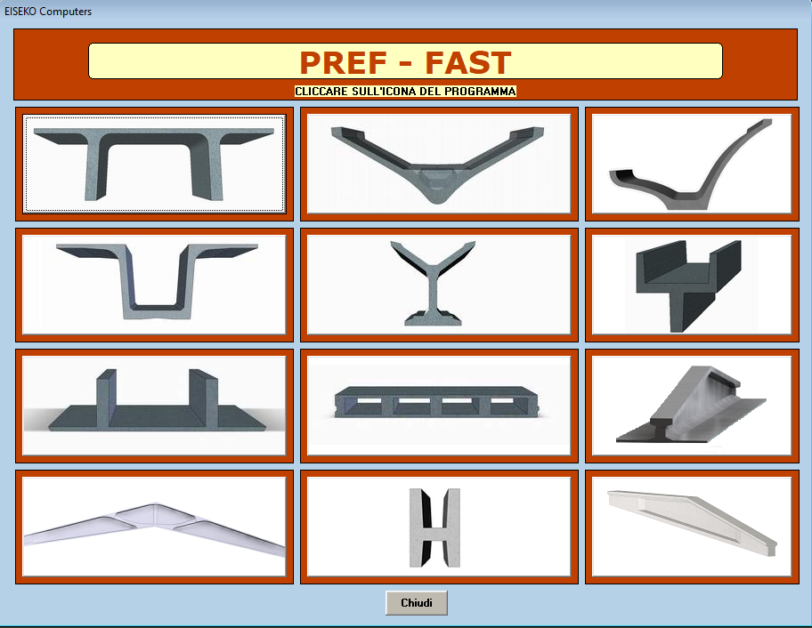
PREF-FAST: CUSTOM PROGRAMS WITH DESIGN, CHECK AND DRAWING OF ANY KIND OF ELEMENT with ANY KIND OF SLOPE.
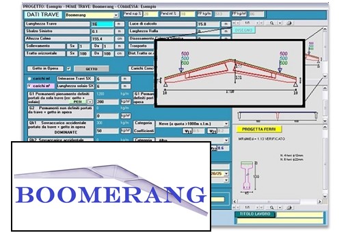
- Boomerang
- Shed (ASYMMETRIC BEAMS)
- Double Tees
- Inverted Double Tees
- WINGSPANS
- Generic covering beams Y, H…
- Beams with non linear slope
- Eaves
- Double slope prestressed beams
- Double slope reinforced conc. beams
- Slabs
- Floors
Other programs on demand

The PREF program is a suite of modules for the calculation of prestressed beams of various gometry which is distributed on an annual subscription basis.
The subscription can be customized, choosing the modules of your interest, and includes the use of the programs, technical assistance and all the updates that will be released.
To reactivate a subscription, simply send us an email request, specifying whether the programs to be included in the package are the same or if you want to change them, you will be sent a quote for the new subscription.
There are pros and cons in both cases, the choice is very personal, but we recommend working on files.
If you work with file, you can save the file wherever you want, on the local PC or on the network (for example in the job order folder). When you create a new file of the project with the calculation program, you will have to manually select the text file of the section (created with the Geometries module) from the folder in which it was saved in. If you work on files it is good habit to make a backup of the project txt files in order not to lose the work you've done.
If you work with database you have all the beams (created with the Geometries program) and the projects (created with the calculation program) saved in the same file, whose management is automatic by the program and you don't have to worry about where you save it (you can see name and path of the file in the "Information" menu). The list could become very long. Anyway, you can do all the operations of saving multiple databases, using databases on the network, changing databases.
If you are working with a database you need to remember to make a backup of the mde / mdb files you used. The files must be saved in a folder on the PC where the user has all access privileges (modification and saving), we recommend C:\Users\Public\Public Documents\Eiseko Database (folder created by default with the installation of the program).
In the menu at the top right select "Data Input", "CompanyData"
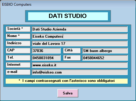
Enter the desired data and press "Save".
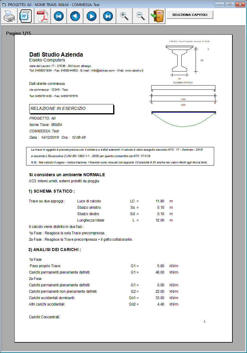
In the menu at the top right select "Data input", "User data"
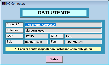
Enter the desired data and press "Save".

Yes, it is possible. It must be done BEFORE creating all the projects belonging to a specific job order.
From the main form, press “SETTINGS” and then “SET SEISMIC PARAMETERS”.
It will open then following window, in which it is possible to associate all the seismic data relating to the location of the selected job.
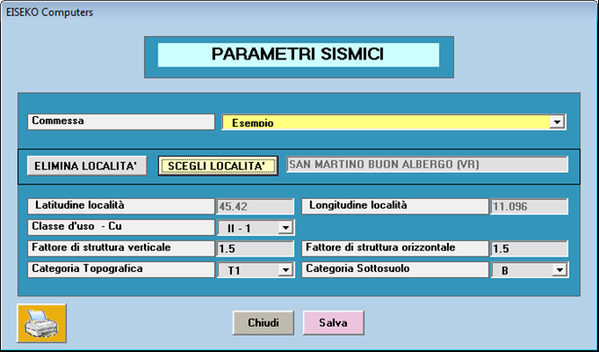
Each time a new project associated with the “Example” job is created, the program will automatically propose the data of the seismic parameters (they will obviously be modifiable).
NOTE: projects that already existed before these parameters are set will continue to use the previously saved data.
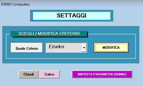
Nella finestra SETTAGGI della finestra iniziale si può impostare il tiro del banco trefoli.
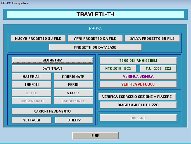
Qua premere MODIFICA
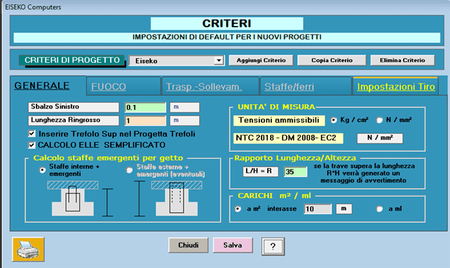
Qua selezionare la scheda IMPOSTAZIONI TIRO
Quindi premere il pulsante arancione SETTAGGI DEFAULT
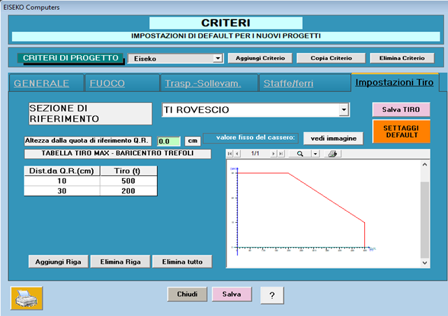
Il programma RTL dà un messaggio di errore se il tiro trefoli complessivo supera i limiti imposti in “Impostazioni Tiro”.
Se si hanno a disposizione i valori del prefabbricatore si possono impostare quelli, la quota di riferimento Q.R. è spiegata, basta premere il pulsante "Vedi immagine", in alto a destra, e si ottiene questa finestra descrittiva.
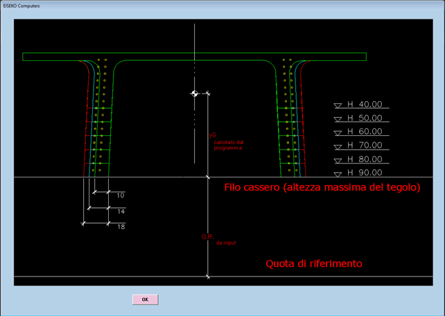
I prefabbricatori hanno il progetto delle testate di tiro dei loro banchi di casseri.
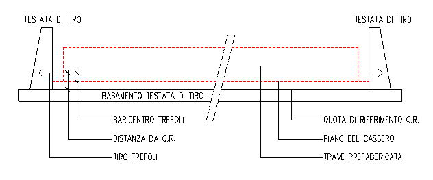
Le testate sono delle strutture vere e proprie in calcestruzzo od acciaio a cui vanno appoggiati i martinetti durante la tesatura e a cui vanno fissati i trefoli prima di effettuare il getto delle travi nei casseri. Le testate devono reggere il tiro complessivo fino all’atto del taglio o del rilascio dei trefoli.
Il progettista delle testate le ha dimensionate in funzione di un tiro massimo dei trefoli variabile in altezza riferito ad una quota che stabilisce lui, che in genere è il piede dei contrafforti.
Si riporta uno schema indicativo.
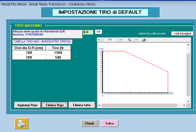
Se non si hanno i valori del prefabbricatore si possono impostare dei valori a caso sufficientemente alti, per esempio Dist. Da Q.R. = 200 cm e Tiro = 1000 ton.
Si procede con: Elimina tutto, si impostano i valori e poi si procede con Aggiungi, Elimina Riga.
Si riporta un esempio
Tutti i “dati di default”, in gruppo, possono essere memorizzati in diversi “CRITERI”: ad es, se un ingegnere lavora per più ditte, può memorizzare i dati di default validi per le diverse ditte in più criteri ciascuno con il nome della ditta. Prima di creare il nuovo progetto scegliere il Criterio della ditta per cui si realizza il progetto di calcolo. L’uso dei “Criteri” si dimostra particolarmente utile per gli schemi di sollevamento e trasporto che possono variare da una ditta all’altra.
Yes, it is possible from version 21.00.00.
If you have a previous version just update the program and then you will be able to select "Verify Existing" in the materials window.
Per poter installare il software la invitiamo a:
- Scaricare il file di installazione tramite il seguente link: PREF_-_INSTALLAZIONE
- Avviare l'eseguibile e seguire i passaggi
- Sul desktop viene creata una icona. Fare doppio click per lanciare il programma
- Inserire la mail fornita al momento dell'acquisto e cliccare su Reset Password
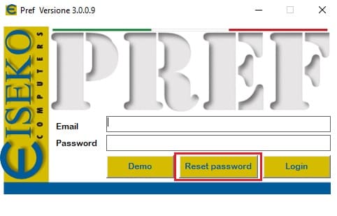
- Una volta ricevuta la password via mail, inserirla nel campo e cliccare su Login
- I software acquistati risulteranno attivi
La invitiamo a contattarci per poter fissare un appuntamento. Verrà assistito da remoto durante l'installazione.
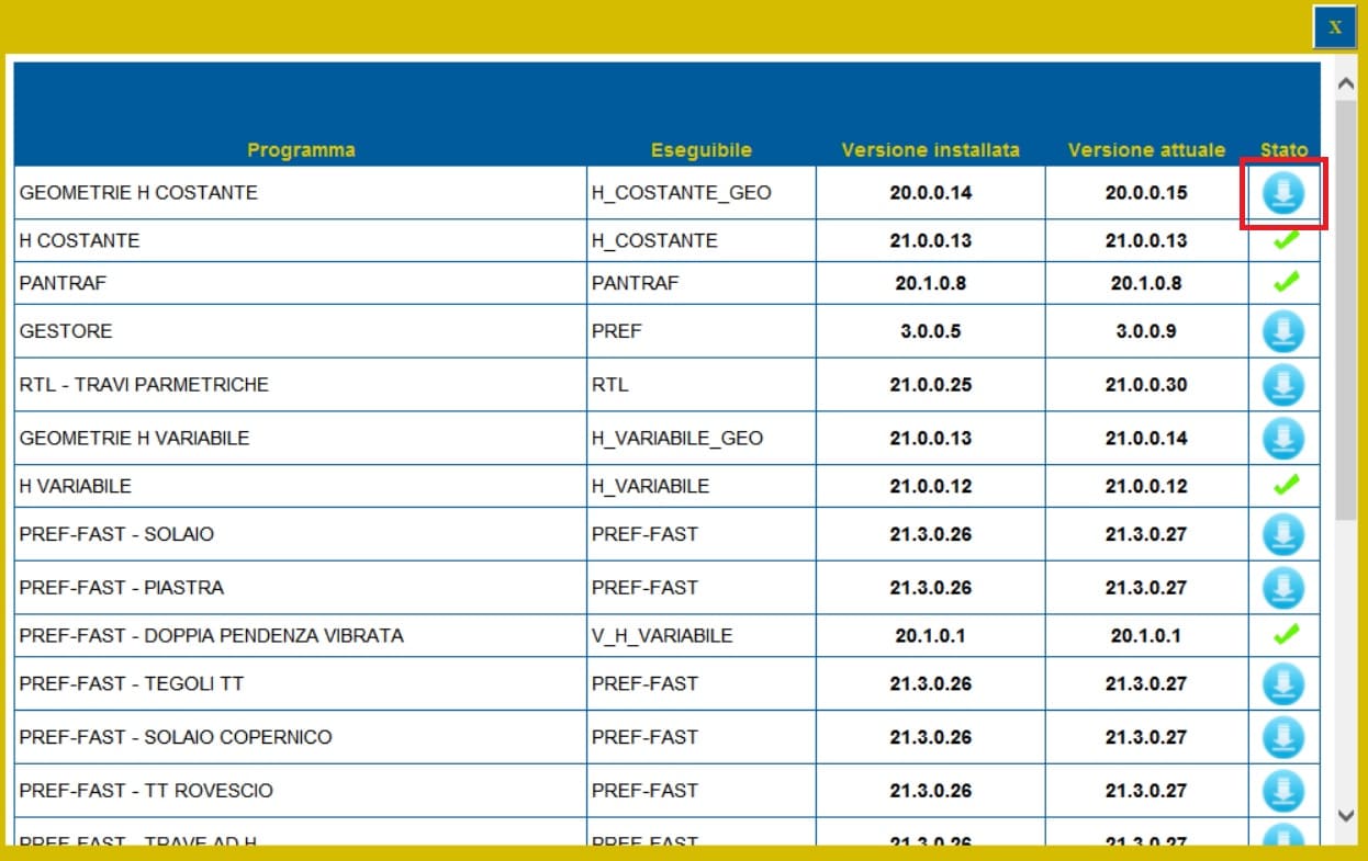
Dopo aver effettuato il Login, cliccare sull'icona "Controlla Aggiornamenti"

Se sono disponibili aggiornamenti, cliccare sull'icona indicata in seguitto per effettuare il download.
Cliccare su Salva
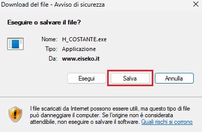
e salvare nella cartella C:\Programmi (x86)\EISEKO sostituendo il file esistente.
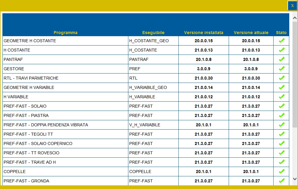
Se dopo aver effettuato l'aggiornamento non viene ancora visulizzata la spunta verde, chiudere la finestra degli aggiornamenti e riaprila.
Se disponibili aggiornamenti per più programmi, ripetere le precedenti operazioni.
Ora tutti i programmi sono aggiornati
!!! Attenzione !!! Per aggiornare il modulo GESTORE salvare il programma in una cartella diversa da 'C:\Programmi (x86)\EISEKO', chiudere il PREF e poi spostarlo manualmente
- Scaricare il file ResetPrefKey tramite il seguente link: PREF_-_RESET LICENZA
- Avviare l'eseguibile
- Cliccare su RESET
- Avviare il software PREF dall'icona sul desktop
- Effettuare nuovamente il Login
- I software acquistati risulteranno nuovamente disponibili
E' necessario cliccare sul tasto Disconnettersi ed effettuare nuovamente il Login:
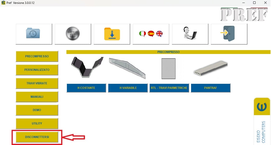
Nel caso in cui la procedura non dovesse avere esito positivo, la invitiamo a seguire i seguenti passaggi:
- Scaricare il file ResetPrefKey tramite il seguente link: PREF_-_RESET LICENZA
- Avviare l'eseguibile
- Cliccare su RESET
- Avviare il software PREF dall'icona sul desktop
- Effettuare nuovamente il Login
- I software acquistati risulteranno nuovamente disponibili
The licensing and updating mode of Eiseko programs has undergone changes: the protection key will no longer be usable. With the new system, you will be able to manage your online license using login credentials.
We invite you to contact us in order to make an appointment. You will be assisted remotely during the installation.
PREF Free Download
Please fill in the form below and we will send you an email with the link to download the FREE version of the software and all the instructions to the email address you entered.
Information request
Please fill in the following form, our staff will answer as soon as possible to the email address you entered.
News, events and promotions
IDEA StatiCa festeggia i suoi 10 anni di CBFEM e dal rilascio di IDEA Connection!
UN DECENNIO DEDICATO ALLA PROGETTAZIONE AVANZATA DELLE CONNESSIONI Festeggia con noi i 10 anni di progettazione delle connessioni con IDEA StatiCa e…
IDEA StatiCa festeggia i suoi 10 anni e rilascia la nuova v24.0
E' stata uscita la nuova versione 24.0 di IDEA StatiCa. Festeggiamo i 10 anni dal rilascio del metodo CBFEM e di IDEA StatiCa Connection e…
FIERA SED | CASERTA | 11 -13 Maggio 2023
Saremo presenti al SED 2023 che si terrà a CASERTA dall'11 al 13 Maggio. Eiseko ti permetterà di partecipare a…

 CYPE Architecture: Software Bim gratuito
