 CYPE Architecture: Software Bim gratuito
 IDEA StatiCa Steel: Steel connections & joints
 GEO5: Geotechnical software
 IDEA BIM: BIM structural software
 ZWCAD: 2D and 3D POWERFUL CAD
 PREF: Prestressed beams
 IDEA Detail: Details in reinforced concrete
 FIN EC: Structural Design Software
 AGACAD: Bim solutions for Revit® professionals
 IDEA StatiCa Concrete: Reinforced concrete design
 IDEA Prestressing: Calculation precast elements
 Tools for ZWCAD: Strumenti per la produttività
 EurocodeExpress: Eurocodes Calculation
 BETONexpress: Reinforced Concrete
 WOODexpress: TIMBER structures
 STEELexpress: Calculation of STEEL elements
 STEELPortalFrame EC3: STEEL Portal Frames Calculation
 SteelSectionsEC3: Design tables for Steel Sections
 3DMacro: Masonry calculation
 Histra Arches and Vaults: Historical Structures Analysis
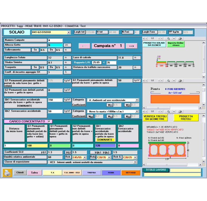
PANTRAF: PROGRAM FOR THE CALCULATION AND DESIGN OF HOLLOWCORES
Simple HOLLOWCORE slabs with semi-rigid joints, placed in continuity
UP TO 4 SPANS + OVERHANGS
Calculation according to Eurocode 2 UNI EN 1992-1-1 version 2005 and Italian NTC 17-01-2018.
AUTOMATIC DESIGN OF THE HOLLOWCORE:
IF YOU THINK 10 SECONDS ARE TOO MUCH, PANTRAF CAN CHOOSE, FROM A LIST DEFINED BY THE USER, THE RIGHT HOLLOWCORE WITHIN 4 SECONDS, JUST THE TIME TO WRITE SPAN AND LOADS. PANTRAF WILL PROPOSE THE HOLLOWCORE TYPE, THE NUMBER OF HOLES TO FILL, MINIMUM REBARS BOTH FOR FLEXION AND SHEAR.
"PAN-TRAF" (HOLLOWCORES) is dedicated to element that are without shear reinforcement (stirrups).
FEATURES OF THE MODULE
- Aggiornati alle nuove normative NTC del 17/01/2018
- PROGETTO AUTOMATICO DEL SOLAIO ALVEOLARE
- FINO A 4 CAMPATE + SBALZI
- Facilissimo da usare e velocissimo
- Risultati completi, evidenziati e facilmente controllabili
- Assistenza tecnica compresa
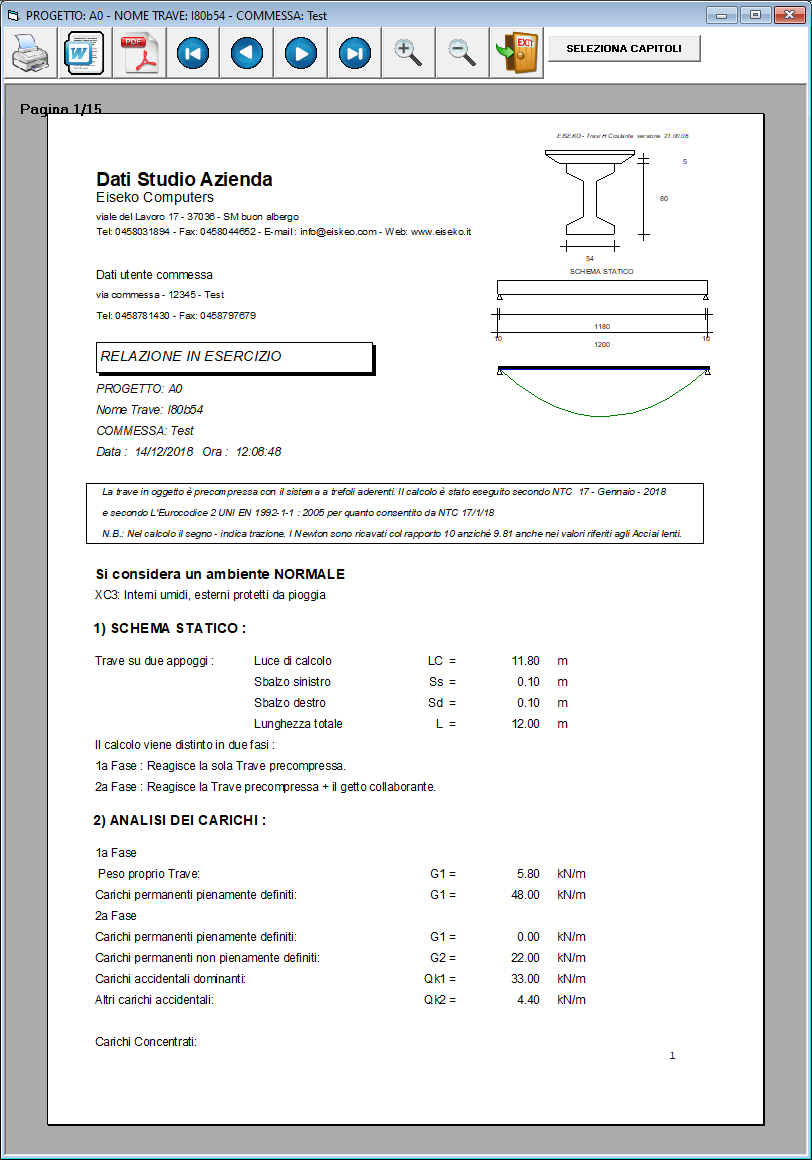
The program verifies and checks iteratively prestressed beams of sections that are symmetrical respect to the vertical axis, according to Eurocode 2 UNI EN 1992-1-1 : 2005 and Italian NTC2018 (ULS, SLS).
Constantly updated to the newest Regulations
ULS Shear verification at supports
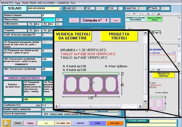
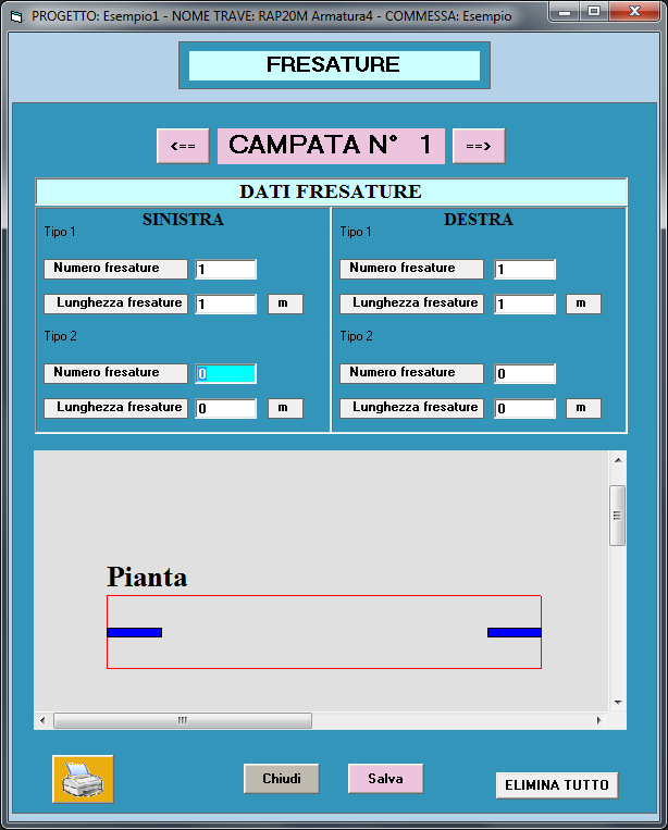
AUTOMATIC FILLINGS OF CORES - The program automatically calculates and highlights the number of cores that are necessary to be filled to verify shear check
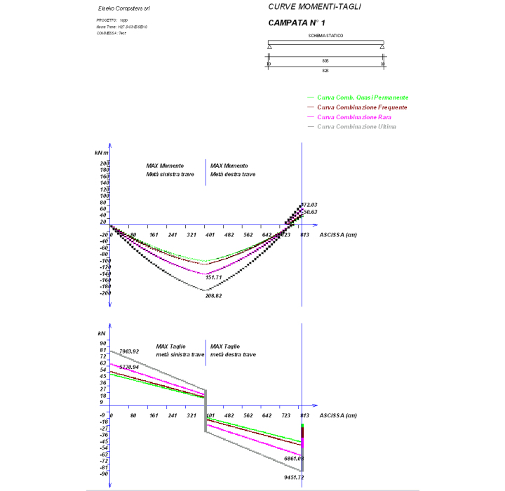
The verification is made in a serie of sections with constant step along the whole beam lenght + the first prestressed section + the most stressed section for bending + the last prestressed section.
Calculation according to Eurocode 2 of the percentage of strands area that can be used as reinforcement anchored on support. This area of reinforcement is used for the checks with cast in place not still solidified, to which necessary reinforcement area is added for the checks with all the loads.
Superior reinforcement
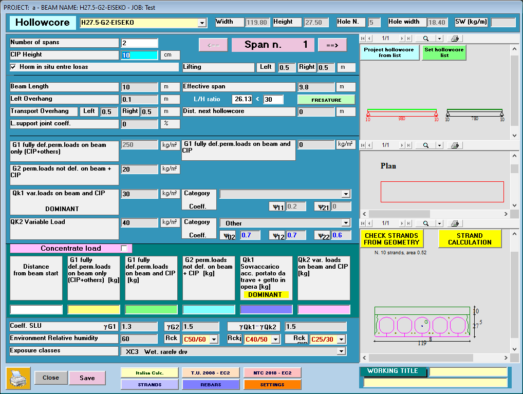
Self-weight of hollowcores and cast in place are automatic or set by user
Joints cast in place CIP concrete between hollowcores is computed for the calculation of composite section properties: for shear and bending moment verifications
Reinforced rebars also in the cast between hollowcores
Possible reduction of the Elastic module of the precast element
Rebar to be grouted in for negative bending moment (tension at extrados)
Shear verification EN1168
Shear verification at midspan
At the ends of the beam it's possible to input a percentage of joint
The program will also verify the transitional phases: the draft, lifting, lifting / transport after a storage period
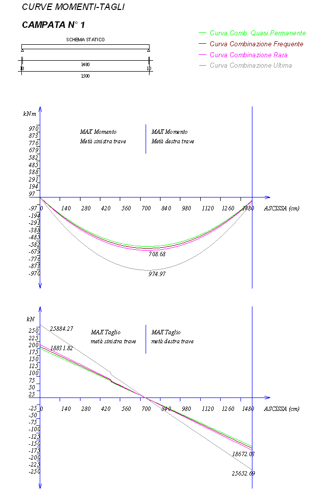
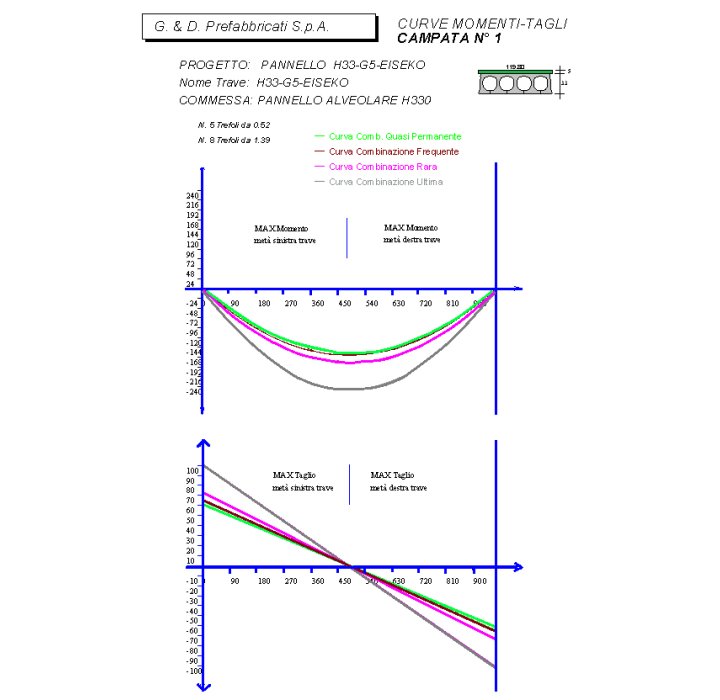
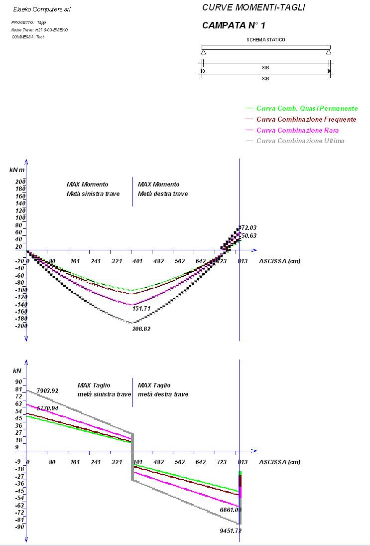
Moment and shear graphs
The losses of tension are calculated in the centre of gravity of the strands contained in the lower 2/3 of the beam. The calculation at limit states is executed in an exact manner based on diagrams of breakage of the strands supplied by the manufacturer of the strands.
In each section the programs checks main traction and compression sigmas on the centre of gravity and shows the minimum distance where the stirrups should be placed. Superior and inferior reinforcement is always calculated, to absorb the tractions as requested from Regulations.
There is the possibility to calculate any section chosen from the user, with the control of main tau and sigma of traction on the whole height of the section.
Shear Verification in the not-prestressed section on support, following the method “variable strut inclination method”
Display of Constraint reactions Rare and Ultimate left and right (also shown in the calculation report).
USE DIAGRAMS research of the span-capacities diagram, given a certain reinforcement
Verification of overhang support
Verification in partial prestress
SEISMIC VERIFICATION
Verification of GERBER SUPPORT
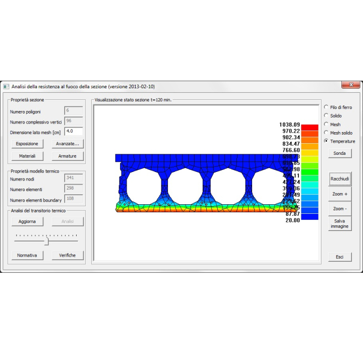
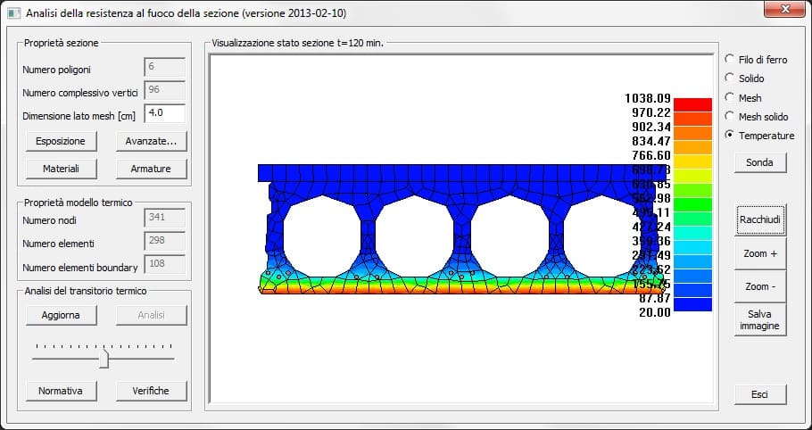
FIRE VERIFICATION
SNOW-WIND LOADS for each Italian location for any load situation.
Calculating the loads, the program adds 1 cm to the beam length to take into account production tolerances. If there is a cast in place and the upper floor width is less than the lower one, the program adds the weight of the cast in place that fills the gap between two near floors.
AUTOMATIC DESIGN OF THE HOLLOWCORE
IF YOU THINK 10 SECONDS ARE TOO MUCH, PANTRAF CAN CHOOSE, FROM A LIST DEFINED BY THE USER, THE RIGHT HOLLOWCORE WITHIN 4 SECONDS, JUST THE TIME TO WRITE SPAN AND LOADS. PANTRAF WILL PROPOSE THE HOLLOWCORE TYPE, THE NUMBER OF HOLES TO FILL, MINIMUM REBARS BOTH FOR FLEXION AND SHEAR.
AUTOMATIC PROJECT OF THE NEEDED STRANDS The program designs the minimum needed pre-tended strands FOR BREACKING VERIFICATION
Automatic calculation of all the geometrical characteristics
The beam can have CAST IN PLACE and POINT LOADS. User can input piece of rebars in any point of the beams
Editing of a database of the most used roof elements for the automatic calculation of G1, so that the user doesn’t need to look through weight tables each time
Input of loads on beam using m2 or m, user choice
Reports and tables can be exported as: DOC, RTF, PDF, HTML
Fast check or results with highlight of eventual values over the limits of the Rules, any values NOT verified are indicated in red, while the values shown in blue are the values within the limits
Graph of the minimal needed area of stirrups along the whole beam
Easy and graphic management of strands, rebars and sheaths.
Handy starting menu
Settings of defaults data can fasten the inputs of the most used configurations of beams
For users that works for more companies, it is possible to save all the default data and the parameters depending on the Company in "Criterions", so that it is easier and fast to switch from a job to another without worring about all settings. For example., it is possible to save any number of lifting ans transportation schemas.
It is possible to switch from one section to another for the verification in a few seconds and immediately see if it is satisfied or not.
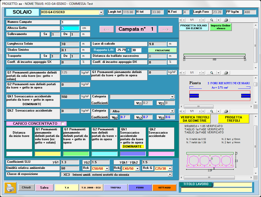
SCHEME OF THE BEAM: in every moment current section, cast in place if present, rebars, pre+post tensed strands and calculation results are displayed to always keep the situation under control.
FREE ADD-INS FOR ALL PROGRAMS engineers can easily and quickly make daily calculations
- CALCULATION OF THE REBARS AREAS (for one or more rebars, to add them and to calculate the rebar area/m)
- TABLE OF REBAR AREAS
- TABLE OF STRAND AREAS
- UNIT OF MEASURE CONVERSION
- SEISMIC PARAMETERS
- SNOW-WIND LOADS for each Italian location for any load situation.
SO FAST IT CAN BE USED ALSO IN THE QUOTING STEP
Lots of enhancements are made according to customer request
Available Languages : Italian, English, Spanish

#1.1. Peso proprio alveolare e getto integrativo del giunto
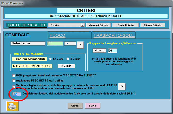
#1.4. Riduzione del modulo elastico del prefabbricato
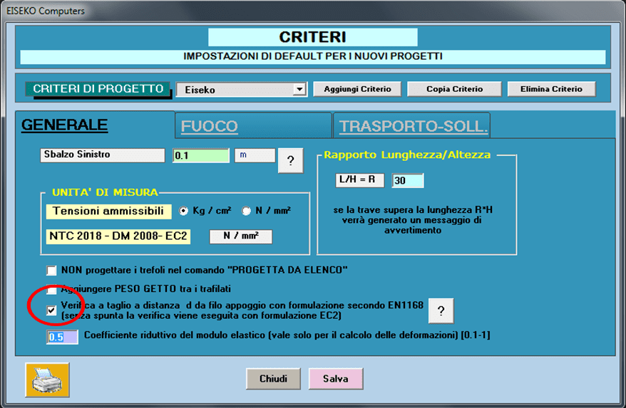
#1.5. Verifica a taglio EN1168
#1.7. Verifica a taglio in campata
#1.8. Verifica a taglio in campata
#Aggiornamento verifica appoggio per NTC 2018
Peso proprio alveolare e getto integrativo del giunto
Possono essere imposti dall’utente nella fase di definizione della sezione, nel Modulo Geometrie, altrimenti vengono calcolati dal programma sulla base delle geometrie teoriche.
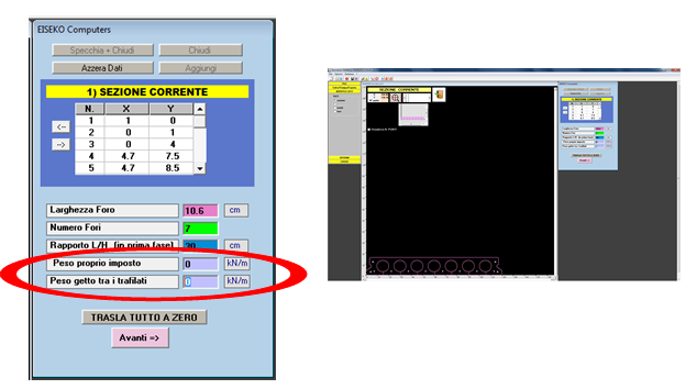
Getto del giunto
Viene considerato per l’aumento della larghezza bw nel calcolo del taglio e delle caratteristiche geometriche di seconda fase.

Spezzoni integrativi
Possono essere inseriti a cura dell’utente nel getto tra i giunti. Il programma li mette in conto solo nelle verifiche in seconda fase, cioè con i carichi successivi alla solidarizzazione del getto in opera.
Riduzione del modulo elastico del prefabbricato
Per tener conto dell’effetto sul modulo elastico E del calcestruzzo, dovuto alla maturazione accelerata dei getti in stabilimento, è stato introdotto un coefficiente riduttivo, variabile da 0.6 a 1.
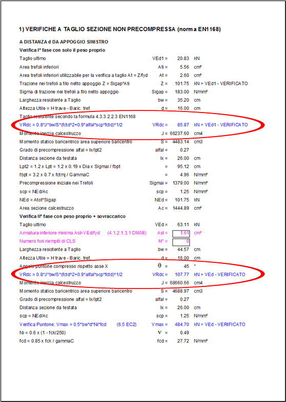
Verifica a taglio EN1168
E’ stata aggiunta la possibilità di fare la verifica a taglio a filo d dall’appoggio usando la formulazione EN1168. La formulazione viene utilizzata anche per la prima fase, in cui si può fare conto del solo prefabbricato.
Appare una stampa di questo tipo
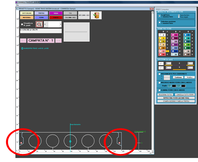
Armatura al negativo
Dalla tabella del calcolo, cliccare su Relazione Continua
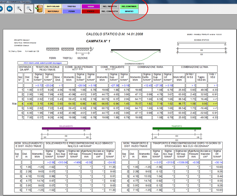
Appare questa videata in cui è calcolata l’armatura superiore:

Verifica a taglio in campata
Il programma differenzia la verifica a taglio in campata a seconda che la sezione sia interamnete reagente o fessurata.
Se è interamente reagente utilizza la formulazione dell’EC2 o dell’EN1168 a seconda della scelta dell’utente. Se viene superato il limite a fessurazione all’intradosso oppure all’estradosso viene usata la formulazione EC2.
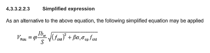
Verifica a taglio sezione interamente reagente
Formule 6.4 EC2, oppure 4.1.24 NTC 2018 valida in Italia.
Oppure formulazione EN1168, vedi qui sotto.
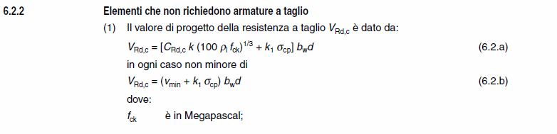
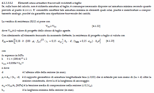
Verifica a taglio sezione fessurata
Formule tratte dal paragrafo 6.2.2 EC2, vedi qui sotto.
Verifica a taglio in campata
Il programma differenzia la verifica a taglio in campata a seconda che la sezione sia interamente reagente o fessurata.
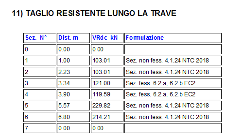
Nella relazione finale appare questo paragrafo che specifica per ogni sezione la formulazione adottata.
Aggiornamento verifica appoggio
Le nuove NTC del 2018 hanno variato la verifica sull’appoggio effettuando una modifica chiarificatrice di un punto un po’ controverso. La nuova espressione, riportata qua sotto, è allineata con la formulazione proposta dall’Eurocodice 2.
Con questa nuova impostazione il programma confronta il taglio resistente fornito dall’armatura, mediante il termine rol, con un valore di taglio resistente minimo che è sempre presente sull’appoggio.
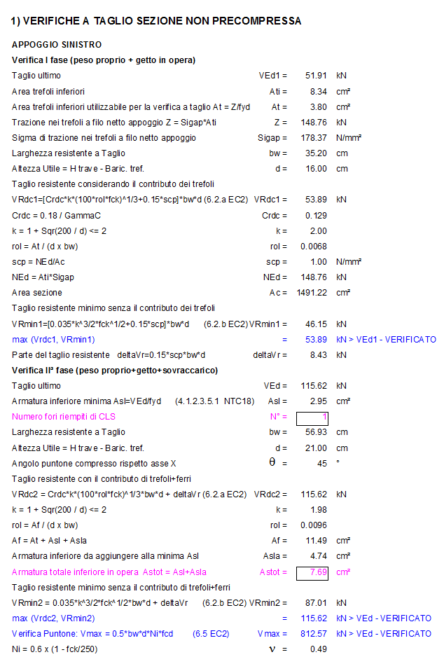
Riassumo il procedimento di verifica sull’appoggio, ai sensi delle NTC del 2018.
Prima fase
Carichi : peso proprio + getto
Si considera reagente la sola sezione precompressa,
Il programma calcola quanta armatura di precompressione è attiva al filo netto dell’appoggio, calcola il rol corrispondente e quindi calcola Vrdc e Vmin in prima fase. Prende il massimo dei due e lo confronta con il taglio di questa fase.
Qui di seguito è riportata una stampa di verifica di esempio.
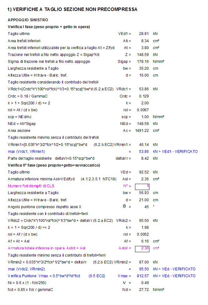
Seconda fase
Carichi : tutti
Si considera reagente la sezione precompressa omogeneizzata al getto nei giunti e al getto della cappa.
Il programma calcola quanta armatura lenta è necessario mettere all’appoggio, mediante la formula VSLU/fyd, la aggiunge all’area di trefoli messa in conto nella prima fase, calcola il rol corrispondente e quindi calcola Vrdc e Vmin in seconda fase. Prende il massimo dei due e lo confronta con il taglio di questa fase.
Se necessario il programma aggiunge fori riempiti.
Se l’utente ha imposto un dato numero di fori riempiti, in questo esempio 1 per testata, il programma aumenta il ferro sull’appoggio rispetto al valore fornito dalla VSLU/fyd.

Nell’esempio che segue ai 2.95 cm2 minimi necessari, occorre aggingere altri 4.74 cm2 di ferro per verificare l’appoggio, per un totale di 2.95+4.74 = 7.69 cm2 in opera.

The PREF program is a suite of modules for the calculation of prestressed beams of various gometry which is distributed on an annual subscription basis.
The subscription can be customized, choosing the modules of your interest, and includes the use of the programs, technical assistance and all the updates that will be released.
To reactivate a subscription, simply send us an email request, specifying whether the programs to be included in the package are the same or if you want to change them, you will be sent a quote for the new subscription.
There are pros and cons in both cases, the choice is very personal, but we recommend working on files.
If you work with file, you can save the file wherever you want, on the local PC or on the network (for example in the job order folder). When you create a new file of the project with the calculation program, you will have to manually select the text file of the section (created with the Geometries module) from the folder in which it was saved in. If you work on files it is good habit to make a backup of the project txt files in order not to lose the work you've done.
If you work with database you have all the beams (created with the Geometries program) and the projects (created with the calculation program) saved in the same file, whose management is automatic by the program and you don't have to worry about where you save it (you can see name and path of the file in the "Information" menu). The list could become very long. Anyway, you can do all the operations of saving multiple databases, using databases on the network, changing databases.
If you are working with a database you need to remember to make a backup of the mde / mdb files you used. The files must be saved in a folder on the PC where the user has all access privileges (modification and saving), we recommend C:\Users\Public\Public Documents\Eiseko Database (folder created by default with the installation of the program).
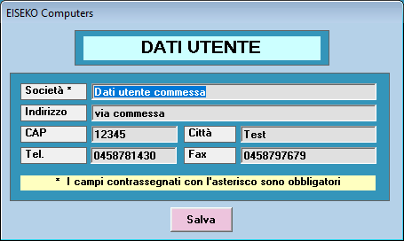
In the menu at the top right select "Data Input", "CompanyData"
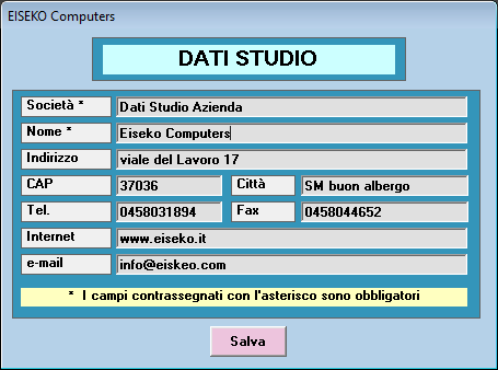
Enter the desired data and press "Save".
In the menu at the top right select "Data input", "User data"
Enter the desired data and press "Save".
Yes, it is possible. It must be done BEFORE creating all the projects belonging to a specific job order.
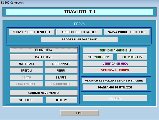
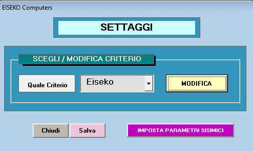
From the main form, press “SETTINGS” and then “SET SEISMIC PARAMETERS”.
It will open then following window, in which it is possible to associate all the seismic data relating to the location of the selected job.
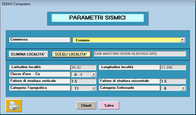
Each time a new project associated with the “Example” job is created, the program will automatically propose the data of the seismic parameters (they will obviously be modifiable).
NOTE: projects that already existed before these parameters are set will continue to use the previously saved data.
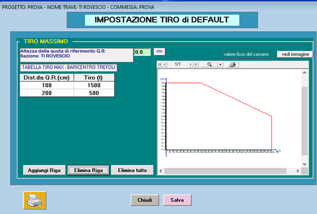
Nella finestra SETTAGGI della finestra iniziale si può impostare il tiro del banco trefoli.
Qua premere MODIFICA
Qua selezionare la scheda IMPOSTAZIONI TIRO
Quindi premere il pulsante arancione SETTAGGI DEFAULT
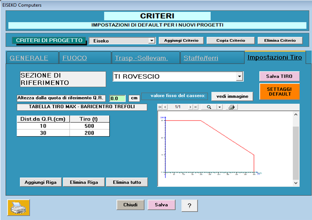
Il programma RTL dà un messaggio di errore se il tiro trefoli complessivo supera i limiti imposti in “Impostazioni Tiro”.
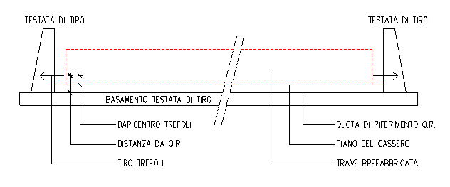
Se si hanno a disposizione i valori del prefabbricatore si possono impostare quelli, la quota di riferimento Q.R. è spiegata, basta premere il pulsante "Vedi immagine", in alto a destra, e si ottiene questa finestra descrittiva.
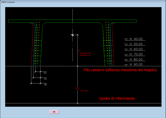
I prefabbricatori hanno il progetto delle testate di tiro dei loro banchi di casseri.
Le testate sono delle strutture vere e proprie in calcestruzzo od acciaio a cui vanno appoggiati i martinetti durante la tesatura e a cui vanno fissati i trefoli prima di effettuare il getto delle travi nei casseri. Le testate devono reggere il tiro complessivo fino all’atto del taglio o del rilascio dei trefoli.
Il progettista delle testate le ha dimensionate in funzione di un tiro massimo dei trefoli variabile in altezza riferito ad una quota che stabilisce lui, che in genere è il piede dei contrafforti.
Si riporta uno schema indicativo.
Se non si hanno i valori del prefabbricatore si possono impostare dei valori a caso sufficientemente alti, per esempio Dist. Da Q.R. = 200 cm e Tiro = 1000 ton.
Si procede con: Elimina tutto, si impostano i valori e poi si procede con Aggiungi, Elimina Riga.
Si riporta un esempio
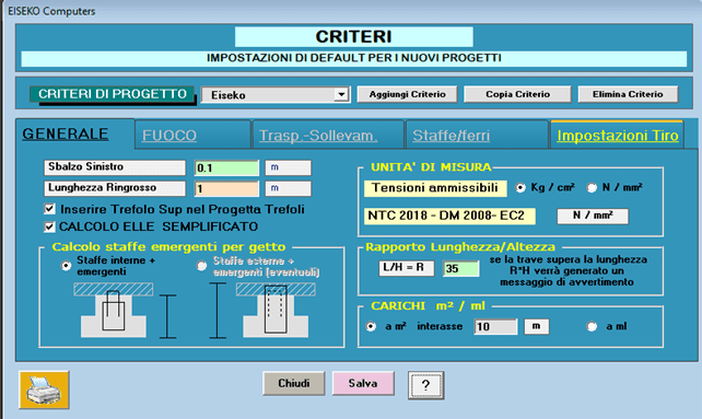
Tutti i “dati di default”, in gruppo, possono essere memorizzati in diversi “CRITERI”: ad es, se un ingegnere lavora per più ditte, può memorizzare i dati di default validi per le diverse ditte in più criteri ciascuno con il nome della ditta. Prima di creare il nuovo progetto scegliere il Criterio della ditta per cui si realizza il progetto di calcolo. L’uso dei “Criteri” si dimostra particolarmente utile per gli schemi di sollevamento e trasporto che possono variare da una ditta all’altra.
Yes, it is possible from version 21.00.00.
If you have a previous version just update the program and then you will be able to select "Verify Existing" in the materials window.
Per poter installare il software la invitiamo a:
- Scaricare il file di installazione tramite il seguente link: PREF_-_INSTALLAZIONE
- Avviare l'eseguibile e seguire i passaggi
- Sul desktop viene creata una icona. Fare doppio click per lanciare il programma
- Inserire la mail fornita al momento dell'acquisto e cliccare su Reset Password
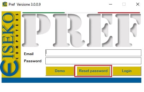
- Una volta ricevuta la password via mail, inserirla nel campo e cliccare su Login
- I software acquistati risulteranno attivi
La invitiamo a contattarci per poter fissare un appuntamento. Verrà assistito da remoto durante l'installazione.
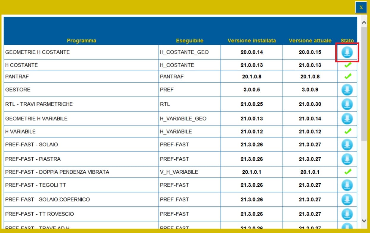
Dopo aver effettuato il Login, cliccare sull'icona "Controlla Aggiornamenti"
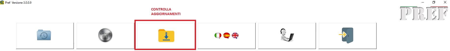
Se sono disponibili aggiornamenti, cliccare sull'icona indicata in seguitto per effettuare il download.
Cliccare su Salva
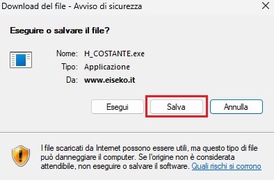
e salvare nella cartella C:\Programmi (x86)\EISEKO sostituendo il file esistente.
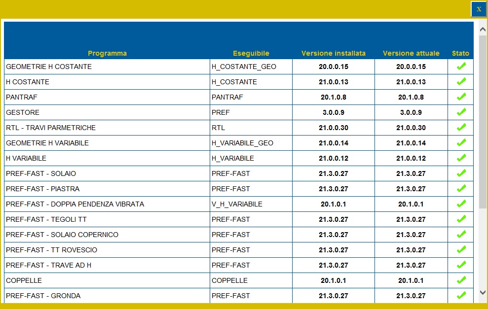
Se dopo aver effettuato l'aggiornamento non viene ancora visulizzata la spunta verde, chiudere la finestra degli aggiornamenti e riaprila.
Se disponibili aggiornamenti per più programmi, ripetere le precedenti operazioni.
Ora tutti i programmi sono aggiornati
!!! Attenzione !!! Per aggiornare il modulo GESTORE salvare il programma in una cartella diversa da 'C:\Programmi (x86)\EISEKO', chiudere il PREF e poi spostarlo manualmente
- Scaricare il file ResetPrefKey tramite il seguente link: PREF_-_RESET LICENZA
- Avviare l'eseguibile
- Cliccare su RESET
- Avviare il software PREF dall'icona sul desktop
- Effettuare nuovamente il Login
- I software acquistati risulteranno nuovamente disponibili
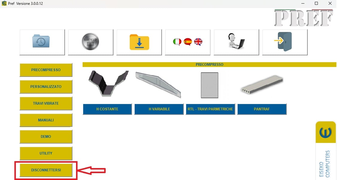
E' necessario cliccare sul tasto Disconnettersi ed effettuare nuovamente il Login:
Nel caso in cui la procedura non dovesse avere esito positivo, la invitiamo a seguire i seguenti passaggi:
- Scaricare il file ResetPrefKey tramite il seguente link: PREF_-_RESET LICENZA
- Avviare l'eseguibile
- Cliccare su RESET
- Avviare il software PREF dall'icona sul desktop
- Effettuare nuovamente il Login
- I software acquistati risulteranno nuovamente disponibili
The licensing and updating mode of Eiseko programs has undergone changes: the protection key will no longer be usable. With the new system, you will be able to manage your online license using login credentials.
We invite you to contact us in order to make an appointment. You will be assisted remotely during the installation.
PREF Free Download
Please fill in the form below and we will send you an email with the link to download the FREE version of the software and all the instructions to the email address you entered.
Information request
Please fill in the following form, our staff will answer as soon as possible to the email address you entered.
News, events and promotions

IDEA StatiCa festeggia i suoi 10 anni di CBFEM e dal rilascio di IDEA Connection!
UN DECENNIO DEDICATO ALLA PROGETTAZIONE AVANZATA DELLE CONNESSIONI Festeggia con noi i 10 anni di progettazione delle connessioni con IDEA StatiCa e…

IDEA StatiCa festeggia i suoi 10 anni e rilascia la nuova v24.0
E' stata uscita la nuova versione 24.0 di IDEA StatiCa. Festeggiamo i 10 anni dal rilascio del metodo CBFEM e di IDEA StatiCa Connection e…

FIERA SED | CASERTA | 11 -13 Maggio 2023
Saremo presenti al SED 2023 che si terrà a CASERTA dall'11 al 13 Maggio. Eiseko ti permetterà di partecipare a…