 CYPE Architecture: Software Bim gratuito
 IDEA StatiCa Steel: Steel connections & joints
 GEO5: Geotechnical software
 IDEA BIM: BIM structural software
 ZWCAD: 2D and 3D POWERFUL CAD
 PREF: Prestressed beams
 IDEA Detail: Details in reinforced concrete
 FIN EC: Structural Design Software
 AGACAD: Bim solutions for Revit® professionals
 IDEA StatiCa Concrete: Reinforced concrete design
 IDEA Prestressing: Calculation precast elements
 Tools for ZWCAD: Strumenti per la produttività
 EurocodeExpress: Eurocodes Calculation
 BETONexpress: Reinforced Concrete
 WOODexpress: TIMBER structures
 STEELexpress: Calculation of STEEL elements
 STEELPortalFrame EC3: STEEL Portal Frames Calculation
 SteelSectionsEC3: Design tables for Steel Sections
 3DMacro: Masonry calculation
 Histra Arches and Vaults: Historical Structures Analysis
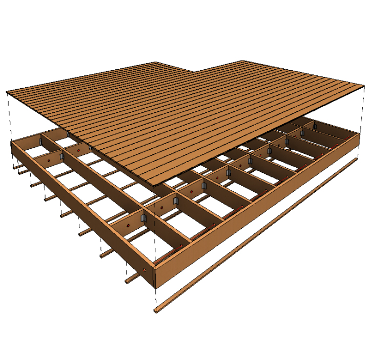
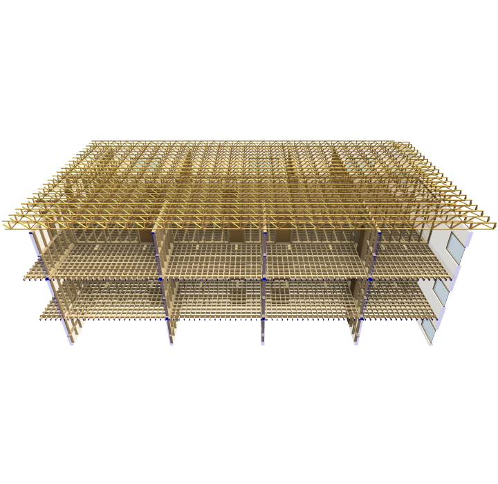
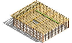
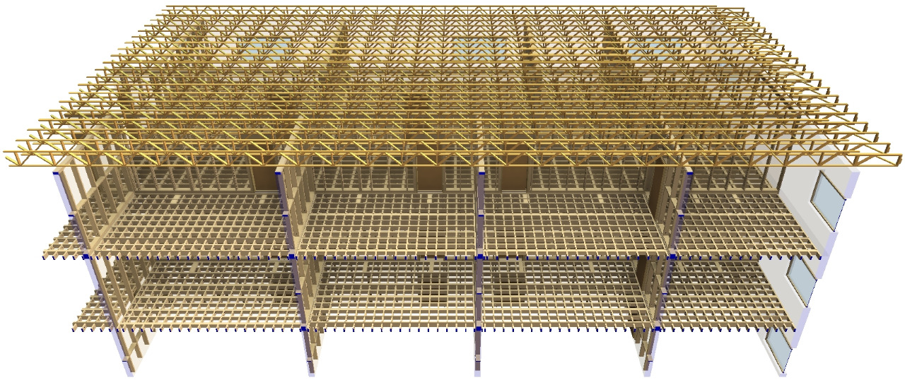
Wood framing floor software for modeling timber floor panels, joists & details in Revit®
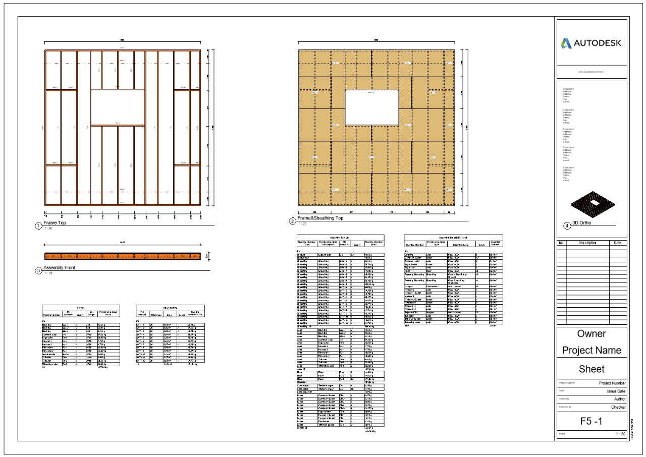
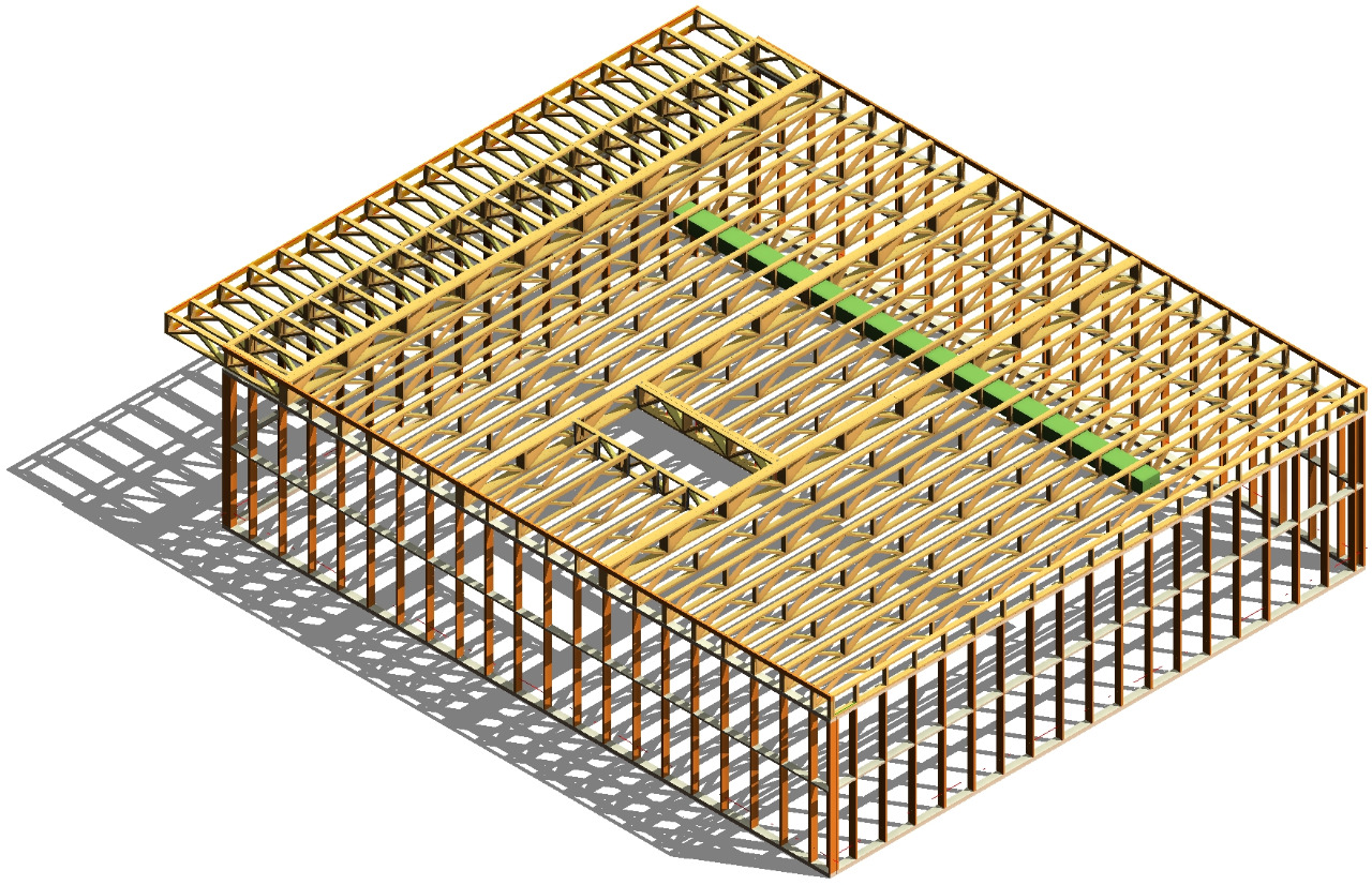
Wood Framing Floor makes framing timber floors fast and easy with real-time full project updates in Revit®. Whether you need to frame multi-layer floors, trussed floors, or panels for prefabrication, this BIM Solution for Revit can do the job. Plus it generates views with automatic dimensions for floor panels or segments as well as accurate bills of materials and shop drawings. So quality production and accurate assembly on site are ensured.
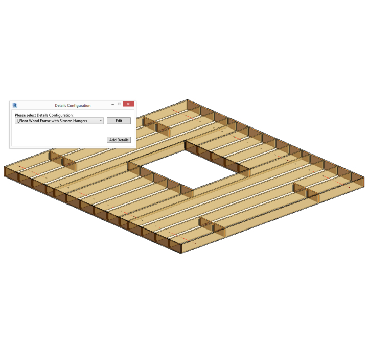
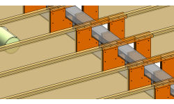
Connectors, cuts, supports, and other details can be distributed based on predefined rules or connection types. They can then be modified or updated to suit the project design stage and the level of detail required. Floor frames and the layout of frame elements and details can be modified and updated whenever the project is changed. Dynamic update functionality can make changes to all floor frames of the same type at once.
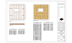
Floor frame elements in the project can be easily marked based on their properties and locations in the floor structure layer. And information for fabrication can be automatically generated with all desired views, schedules, and drawings for each floor segment or panel.
FEATURES OF THE MODULE
- Automatic multilayer floor framing using predefined or custom rules and templates.
- Frame multi-story houses 10 times faster.
- Easily control supporting structure, distribute details, service holes and more.
- Automate sheathing layouts.
- Freely revise your model by selecting the elements and properties to modify.
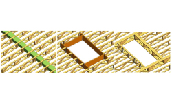
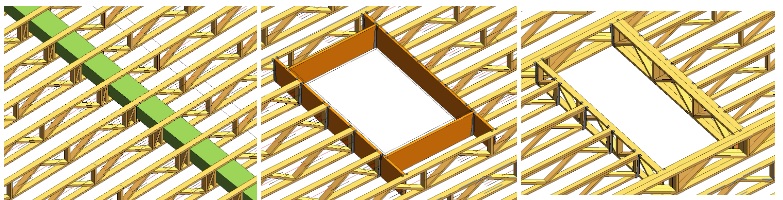
- Find structural and engineering clashes; cut and frame openings according to predefined rules.
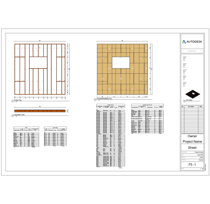
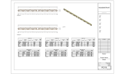
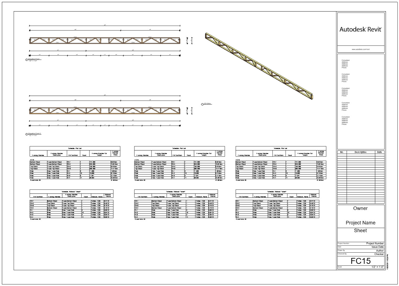
- Easily prepare shop drawings and cut lists, with all required views, where elements are dimensioned, sorted, tagged, scheduled, and mass calculated.
- Optional export to any CNC machines and CAD/CAM production lines, such as WEINMANN, Randek, etc.
- Floor frames update and adapt according to any changes.
- Perform structural analyses without leaving Revit, or export your wood frames to external analysis software at any stage of design process.
Revit® Turbocharger for Timber Frame Floors
Wood Framing Floor+ automates wood framing work with floors in Revit® projects. It’s powerful, flexible and easy to use. It helps you make better decisions, move much faster and avoid errors at every BIM stage – from design and documentation to segment fabrication and construction.
Auto-generate detailed multilayer floor framing for your Revit model using predefined or custom rules and templates
Frame multi-story houses 10 times faster than using standard Revit interface
Easily control supporting structure, including battens and flooring; distribute details, service holes and more
Automate sheathing layouts
Freely revise your Revit model by easily selecting the elements and properties you want to modify
Find structural and engineering clashes; cut and frame openings according to predefined rules
Easily prepare shop drawings and cut lists, with all required views, where elements are dimensioned, sorted, tagged, scheduled, and mass calculated
Optional export to any CNC machines and CAD/CAM production lines, such as WEINMANN, Randek, etc.
Floor frames update and adapt according to any changes
Perform structural analyses without leaving Revit, or export your wood frames to external analysis software at any stage of design process
Part of the AGACAD Wood Framing Floor, a dynamic set of solutions which leverage the full potential of Revit and the insights of global BIM experts. (Wood Framing Suite is also available for purchase — CONTACT US.)
Selected additional features
• Automated modeling of floor’s wood framing members including joists, battens, bridging, blockings, rims, noggings, and more.
• Fully scalable: from simple structures to complex multi-level buildings with irregular floor shapes.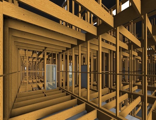
• Easily transfer framing elements between same groups or identical floors in different levels of buildings by predefining which elements the building designer is going to affect: all floors from the same model group, from the instance model group, or selected floor should be unique in the building.
• Framing types easily linked with floor types; can be preset for bearing or non-bearing floors.
• Complex multi-layer floor framing: unlimited number of layers.
• Automated details (support clips, hangers, web stiffeners, service holes, etc.) on bridgings, blockings and rim joists.
• Alignment of joists across floor segments and between floors and walls.
• Floor frame can be modified any time and supplemented with additional members.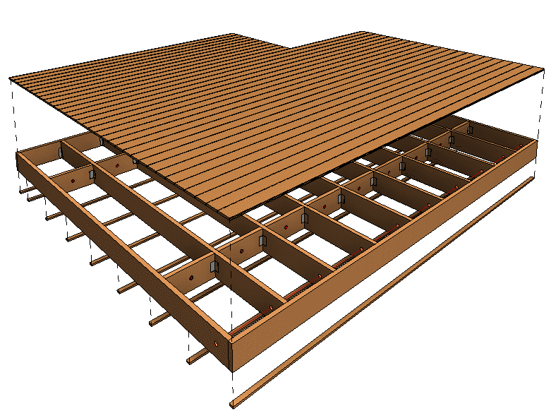
• Sheathing layouts can be easily generated and split by existing joists.
• Built-in clash detection between structural and engineering objects; automated floor openings and flexible framing around it.
• Library with main types of floor framing can be edited and expanded.
• Automatic sorting, tagging, dimensioning, and scheduling (including mass) of all frames and sheathing layouts.
• Shop drawing views and schedules are added automatically to sheets according to user’s predefined template.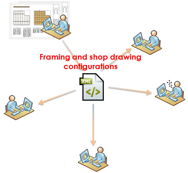
• All templates and rules are fully customizable; framing sheathing and shop drawing configurations can be saved
for future projects and shared between company team members.
• Easy setup, user-friendly interface with intuitive mouse-driven options.
• Optional CNC output (Hundegger, Randek, Weinmann, …) to joinery machines and multi-panel production lines enables your model data to be automatically exported to manufacturing.

Developed in compliance with standards and guidelines:
Eurocode 5: Design of timber structures – Part 1-1: General – Common rules and rules for buildings (EN 1995-1-1:2004: E)
Standards Australia AS 1684.2-2010 Residential timber-framed construction
Standards Australia AS 1720.1-2010 Timber structures – Design methods
New Zealand Standard NZS 3604:2011 / Timber Framed Buildings
CWC (Canadian Wood Council) Wood Design Manual including CSA O86 Standard and CWC Commentary on CSA O86 (2010).
National Design Specification® (NDS®) for Wood Construction (NDS 2015). American Forest and Paper Association (AF&PA). American Wood Council, Washington DC, 2015.
The Encyclopedia of Trusses. Alpine Engineered Products, Inc., 2003.
Truss Design Procedures and Specifications for Light Metal Plate Connected Wood Trusses / TPIC – 2014. Truss Plate Institute of Canada (TPIC), 2014.
Using Narrow Pieces of Wood Structural Panel Sheathing in Wood Shear Walls. American Plywood Association (APA), The Engineered Wood Association, Tacoma, Washington, 2005
Sviluppato in conformità a standard e linee guida:
Eurocodice 5: Progettazione di strutture in legno - Parte 1-1: Generale - Regole e regole comuni per gli edifici (EN 1995-1-1: 2004: E)
Standards Australia AS 1684.2-2010 Costruzione residenziale a graticcio
Standards Australia AS 1720.1-2010 Strutture in legno - Metodi di progettazione
New Zealand Standard NZS 3604: 2011 / Edifici con struttura in legno
Manuale di progettazione del legno del CWC (Canadian Wood Council) incluso lo standard CSA O86 e il commento CWC su CSA O86 (2010).
National Design Specification® (NDS®) per le costruzioni in legno (NDS 2015). Associazione americana della foresta e della carta (AF&PA). Consiglio americano di legno, Washington DC, 2015.
L'Enciclopedia delle capriate. Alpine Engineered Products, Inc., 2003.
Procedure e specifiche per la progettazione di tralicci per travature reticolari in legno collegate con piastra metallica leggera / TPIC - 2014. Truss Plate Institute of Canada (TPIC), 2014.
Utilizzo di pezzi stretti di rivestimento in pannelli strutturali in legno in pareti di legno a taglio. American Plywood Association (APA), The Engineered Wood Association, Tacoma, Washington, 2005
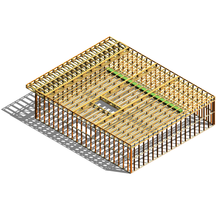
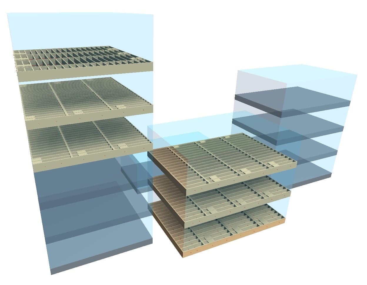
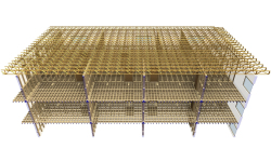
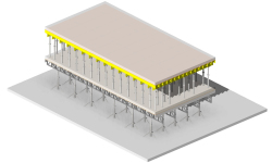
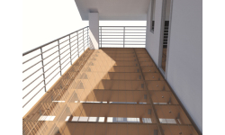
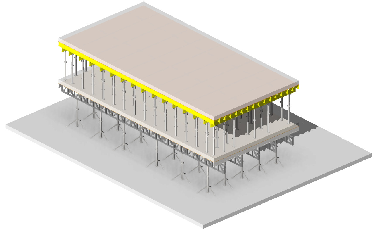
Dalla massa concettuale all'intelaiatura strutturale con pavimento in legno / metallo
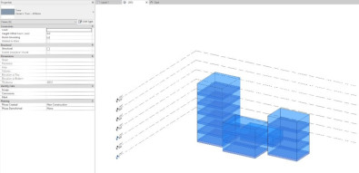
La volumetria è stata ampiamente accettata come mezzo principale per la progettazione di edifici in fase iniziale. L'utilizzo di blocchi di massa per definire la futura forma, dimensione, qualità dello spazio e caratteristiche del design di un edificio è un metodo standard per affrontare un nuovo progetto nella fase di progettazione concettuale. I modelli di volumetria reali sono un ottimo modo per risolvere i problemi relativi ai volumi di un edificio autonomo o di un intero masterplan. Essendo una delle considerazioni più importanti sulla progettazione architettonica, le volumetrie possono influenzare in modo significativo la nostra percezione di un edificio.
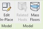
Gli strumenti di volumetria concettuali di Autodesk Revit offrono una grande versatilità per la generazione di masse di qualsiasi forma e dimensione. Lo strumento di volumetria di Revit è spesso un punto di partenza per progetti di qualsiasi dimensione. L'architetto prima sviluppa una massa di uno o più edifici, per poi entrare nei dettagli. In caso di creazione di una massa da zero, Revit offre un ottimo strumento: In-Place Mass (massa sul posto). Essa consente di creare una famiglia di sistema di una massa senza lasciare il file di progetto, e poter lavorare nel contesto del progetto.
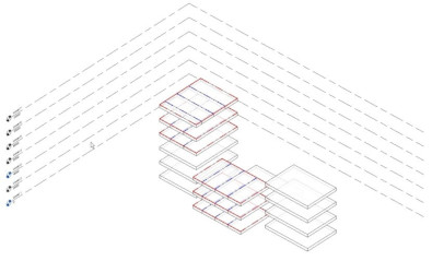
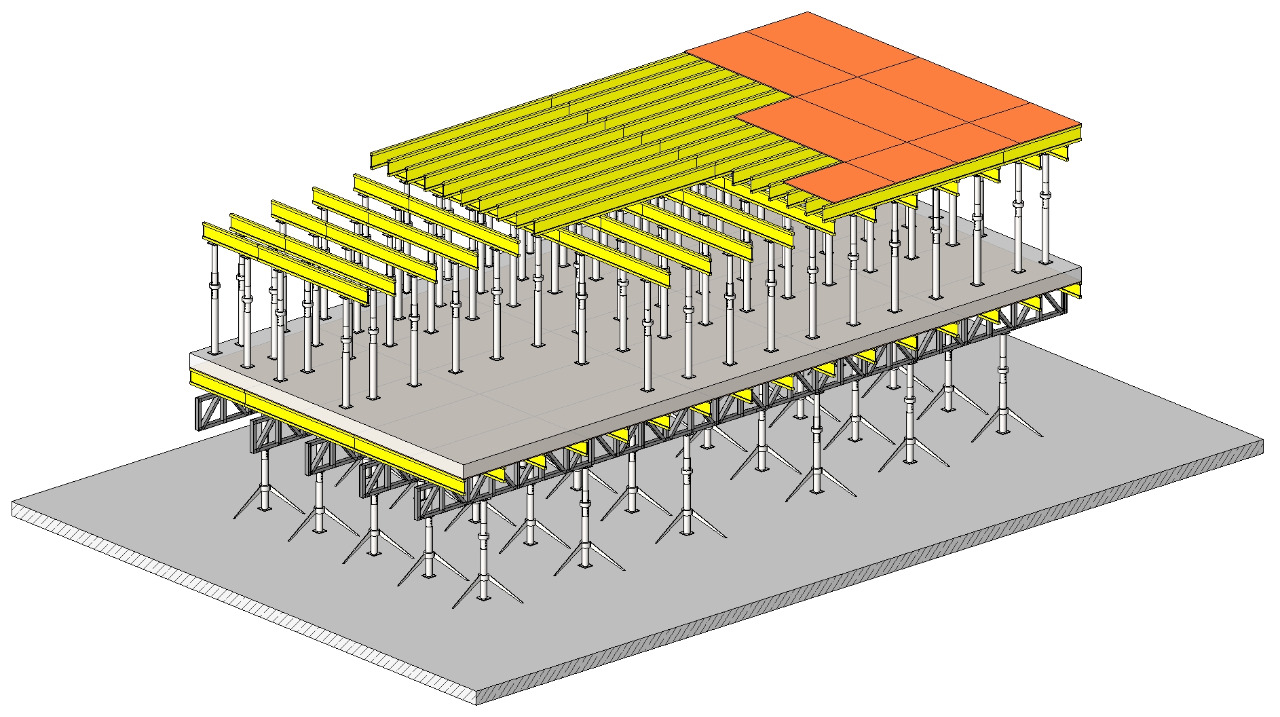
Aggiungi la massa dei solai alle volumetrie di Revit.
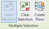
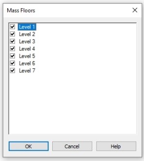
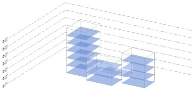
Creare solai in Revit dalla massa dei solai selezionando i solai e selezionando i livelli.
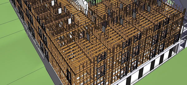
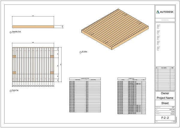
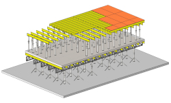
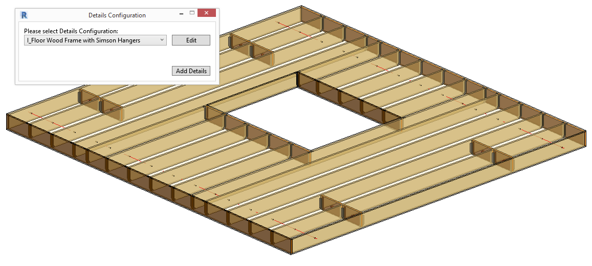
Una volta stabilita la massa, o gruppo di masse, possiamo perfezionare ulteriormente la nostra costruzione applicando la geometria alle masse. Ad esempio, possiamo generare solai dai livelli stabiliti nel progetto. Con i solai applicati alla massa, possiamo utilizzare floor framing di AGACAD per Revit, dividere i solai in pannelli e generare telai strutturali in automatico. Questo tipo di flusso di lavoro consente di generare un telaio strutturale per elementi di edificio come un solaio quando si dispone solo di una massa dell'edificio. Utilizzando la funzionalità Floor+ è anche possibile ordinare gli elementi strutturali e creare assiemi. Può anche generare tavole degli elementi con pochi clic. Un processo così rapido può far risparmiare una grande quantità di tempo quando si incornicia un edificio dalle masse. Floor+ utilizza configurazioni predefinite per il telaio, quindi ogni volta che qualcosa nel progetto cambia, puoi modificare la configurazione esistente e aggiornare automaticamente tutti i tuoi telai.
Framing floor in Revit pone alcune difficoltà. Ad esempio, le famiglie e tutti i tipi di parametri devono essere impostati prima ancora di inquadrare un pannello. Utilizzando la funzionalità Floor+ di AGACAD, è possibile generare un telaio strutturale per un tipo di solaio semplice o complesso e un metodo di costruzione / assemblaggio. La configurazione può essere modificata e aggiornata in qualsiasi momento durante lo sviluppo del progetto.
ELENCO DEI PROGRAMMI INCLUSI IN WOOD FRAMING FLOOR
- Floor+
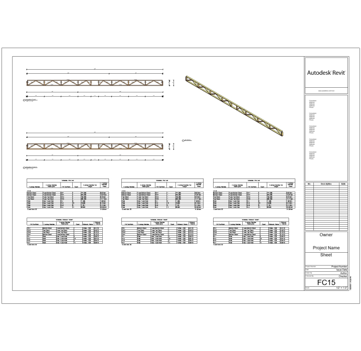
- Truss+
- Cut Opening
- Floor Panel Layout
- Sort Mark
Prodotti abbinabili consigliati per Wood Framing Floor:
- Metal Framing Floor
- Metal Framing Roof
- Wood Framing Wall
- Wood Framing Floor
- Wood Framing Roof
- Wood Framing SIPS
- Smart Browser
- Smart Connections
Per maggiori informazioni, CONTATTACI per un PREVENTIVO PERSONALIZZATO!

AGACAD Free Download
Per favore compila il modulo sottostante e ti invieremo una mail con il link per scaricare la versione FREE del software e tutte le istruzioni all'indirizzo email inserito.
Information request
Please fill in the following form, our staff will answer as soon as possible to the email address you entered.
News, events and promotions

IDEA StatiCa festeggia i suoi 10 anni di CBFEM e dal rilascio di IDEA Connection!
UN DECENNIO DEDICATO ALLA PROGETTAZIONE AVANZATA DELLE CONNESSIONI Festeggia con noi i 10 anni di progettazione delle connessioni con IDEA StatiCa e…

IDEA StatiCa festeggia i suoi 10 anni e rilascia la nuova v24.0
E' stata uscita la nuova versione 24.0 di IDEA StatiCa. Festeggiamo i 10 anni dal rilascio del metodo CBFEM e di IDEA StatiCa Connection e…

FIERA SED | CASERTA | 11 -13 Maggio 2023
Saremo presenti al SED 2023 che si terrà a CASERTA dall'11 al 13 Maggio. Eiseko ti permetterà di partecipare a…